
Uniform barometric pressure micro-plasma discharge device with flow equalizing system

A micro-plasma and discharge device technology, applied in the direction of plasma and electrical components, can solve the problems of complicated maintenance and high cost, and achieve the effects of good current equalization effect, reasonable structure and high stability

Active Publication Date: 2015-12-30
DALIAN NATIONALITIES UNIVERSITY
View PDF10 Cites 3 Cited by
  • Summary
  • Abstract
  • Description
  • Claims
  • Application Information

AI Technical Summary

Problems solved by technology

Most atmospheric pressure low-temperature plasma discharge devices need to use complex gas paths or electrode arrangements to achieve stable plasma discharge under atmospheric pressure conditions, often resulting in high costs, cumbersome maintenance, and various problems emerge in endlessly

Method used


Image

  • Uniform barometric pressure micro-plasma discharge device with flow equalizing system

Examples


Embodiment 1

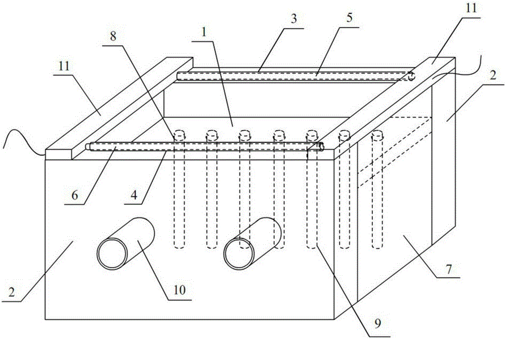
[0030] like figure 1 As shown, the dielectric plate A is in the shape of a cuboid, which contains a cylindrical jack, and the dielectric tube C is inserted into it, which can evenly flow the discharge gas entering from the air inlet. The dielectric plate B is a solid cuboid, and the dielectric plate A is clamped and Use AB glue to connect with the dielectric board A, and use insulating sealing plates to seal the openings on both sides of the two dielectric boards B, so that the whole forms an H-shaped box structure.

[0031] Dielectric tube A opens on the left side and inserts an electrode made of tungsten wire, and the right side opening of dielectric tube B inserts an electrode made of tungsten wire. The electrode in dielectric tube A is used as a high-voltage electrode, and the electrode in dielectric tube B is used as a ground electrode. The dielectric board C is fixed on both ends of the top of the dielectric board B, and plays the role of fixing and insulating. Among th...

Embodiment 2

[0033] The dielectric plate A is in the shape of a cuboid, which contains a cylindrical jack, and the dielectric tube C is inserted into it, which can evenly flow the discharge gas entering from the air inlet. The dielectric plate B is a solid rectangular parallelepiped. The dielectric plate A is clamped and fixed using The method is connected with the dielectric board A, and the openings on both sides of the two dielectric boards B are sealed with insulating sealing plates to form an H-shaped box structure as a whole.

[0034] The left side opening of the dielectric tube A is inserted with an electrode made of copper wire, and the right side of the dielectric tube B is inserted with an electrode made of copper wire. The electrode in the dielectric tube A is used as a high-voltage electrode, and the electrode in the dielectric tube B is used as a ground electrode. The dielectric board C is fixed on both ends of the top of the dielectric board B, and plays the role of fixing and...


PUM


Abstract

The invention relates to a uniform barometric pressure micro-plasma discharge device with a flow equalizing system. The device comprises a dielectric slab A, two dielectric slabs B, a dielectric tube A, a dielectric tube B, a high pressure electrode and a ground electrode, wherein the dielectric slab A and the dielectric slabs B are respectively of a rectangular plate structure, the two dielectric slabs B are in parallel, and sealing plates are mounted between the dielectric slab A and the side edges on the two sides of the dielectric slabs B; the dielectric slab A is horizontally mounted between the two dielectric slabs B; the dielectric tube A and the dielectric tube B are mounted on the top edges of the two dielectric slabs B respectively, the high pressure electrode and the ground electrode are mounted in the dielectric tube A and the dielectric tube B respectively, and the dielectric tube A and the dielectric tube B are opposite in opening direction; a row of jacks are equidistantly formed in the surface of the dielectric slab A, and dielectric tubes C are fixedly connected into the jacks and arranged equidistantly; an admission piece is mounted on the dielectric slab B on one side and communicated with an inner cavity of a box body formed by the dielectric slab A, the dielectric slabs B and the sealing plates. The device has the advantages of being reasonable in structure, good in flow equalizing effect, free of pollution and the like.

Description

technical field [0001] The invention relates to a discharge device, especially a plasma discharge device. Background technique [0002] Atmospheric pressure low-temperature plasma discharge has always been a research hotspot in the field of plasma. How to realize uniform atmospheric pressure low-temperature plasma discharge is a problem we want to solve. Most atmospheric-pressure low-temperature plasma discharge devices need to use complex gas circuits or electrode arrangements to achieve stable plasma discharge under atmospheric pressure conditions, which often results in high costs, cumbersome maintenance, and various problems emerge in endlessly. Contents of the invention [0003] The purpose of the present invention is to provide a uniform atmospheric pressure micro-plasma discharge device with a more uniform and stable plasma discharge and a self-contained current equalization system. [0004] In order to achieve the above object, the following technical solutions ar...

Claims


Application Information

Patent Timeline
IPC IPC(8): H05H1/24
Inventor 宋颖赵曜刘东平
Owner DALIAN NATIONALITIES UNIVERSITY
Learn More