
Rotary motor casing processing fixture

A tooling fixture and rotary technology, which is applied in the direction of manufacturing tools, metal processing equipment, metal processing machinery parts, etc., can solve the problems of unguaranteed position of holes, difficulty in meeting drawing requirements, low product qualification rate, etc., to achieve Reduced processing time, shortened clamping time, and high efficiency

Active Publication Date: 2017-05-17
中色创新研究院(天津)有限公司
View PDF7 Cites 0 Cited by
  • Summary
  • Abstract
  • Description
  • Claims
  • Application Information

AI Technical Summary

Problems solved by technology

The traditional processing method mainly depends on the technical level of the operator. Milling machine, drilling machine and tapping machine are required to process the milling, drilling and tapping of the side of the casing respectively. The labor intensity is high, the processing time is long, and the hole The position degree cannot be guaranteed, and the product qualification rate is relatively low, especially for special-shaped workpieces such as motor casings, the angle between the holes in all directions on the side is difficult to meet the drawing requirements

Method used


Image

  • Rotary motor casing processing fixture
  • Rotary motor casing processing fixture
  • Rotary motor casing processing fixture

Examples


Embodiment

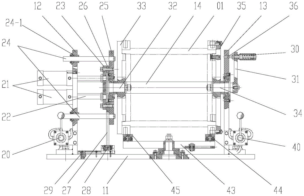
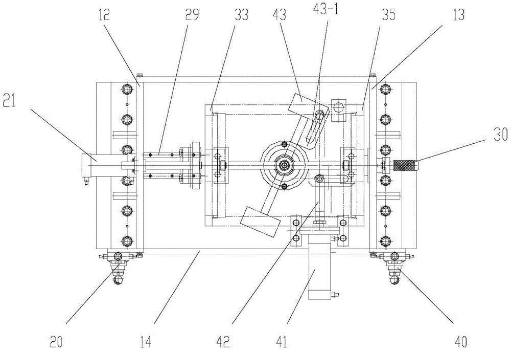
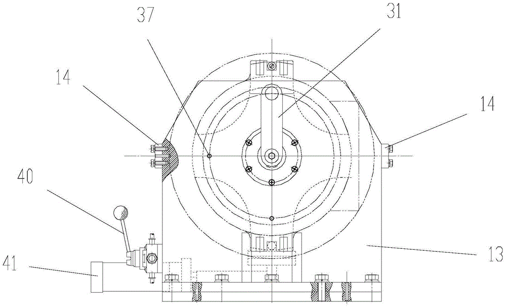
[0021] See the accompanying drawings for details. This embodiment provides a rotary motor casing processing fixture, including a tooling frame mechanism, an axial clamping mechanism, a rotating mechanism, and a bottom support mechanism. The axial clamping mechanism, the bottom support mechanism They are respectively connected with the tooling frame mechanism, and the rotating mechanism is connected with the axial clamping mechanism. The tooling frame mechanism includes a bottom plate 11, a left brace 12, a right brace 13 and a drawstring 14. The left brace and the right brace The plate is fixed by a drawstring, and the left support plate, the right support plate and the bottom plate are vertically fixed to form an overall tooling frame.

[0022] The axial clamping system performs axial fastening on the casing workpiece, including clamping pneumatic switch 20, cylinder 21, cylinder drive rod 22, drive plate 23, guide rod 24, force plate 25, backing plate 26, sliding support Pla...


PUM


Abstract

The invention relates to a rotating motor casing machining tool fixture. The rotating motor casing machining tool fixture is characterized by comprising a tool frame mechanism, an axial clamping mechanism, a rotating mechanism and a bottom support mechanism, wherein the axial clamping mechanism and the bottom support mechanism are respectively connected with the tool frame mechanism; the rotating mechanism is connected with the axial clamping mechanism; a left support plate and a right support plate of the tool frame mechanism are fixed through a pull belt; the axial clamping mechanism axially fastens a casing workpiece; left and right rotating shafts of the rotating mechanism are pinned with left and right clamping plates, and are supported on the axial clamping mechanism through bearings; and the bottom support mechanism upwards supports the casing workpiece. The rotating motor casing machining tool fixture has the following beneficial effects: the axial clamping and the vertical support of an aluminum alloy motor casing are both driven by a cylinder, so that the clamping time is shortened; the pressure control is realized through a pressure adjusting valve to prevent the deformation of a clamped aluminum alloy; and the rotating mechanism realizes once clamping of an aluminum alloy motor casing, and can perform the multi-angle surface milling, drilling and tapping machining for the surface of the casing to improve the production efficiency.

Description

technical field [0001] The invention belongs to machining tooling, in particular to a machining tooling fixture for a rotary motor casing. Background technique [0002] In order to facilitate the installation of the aluminum alloy motor, it is necessary to drill holes at different positions on the side of the motor casing, and the requirements for the shape, position, tolerance and size of the holes are relatively strict. The traditional processing method mainly depends on the technical level of the operator. Milling machine, drilling machine and tapping machine are required to process the milling, drilling and tapping of the side of the casing respectively. The labor intensity is high, the processing time is long, and the hole The position of the machine cannot be guaranteed, and the product qualification rate is relatively low, especially for special-shaped workpieces such as motor casings, the angle between the holes in all directions on the side is difficult to meet the ...

Claims


Application Information

Patent Timeline
Patent Type & Authority Patents(China)
IPC IPC(8): B23Q3/08
CPCB23Q3/062B23Q3/08B23Q2703/04
Inventor 吉冬志李永林吕涛杨永刚刘冲霄杨涛王世全刘福清
Owner 中色创新研究院(天津)有限公司
Learn More