Simple tool setting and alignment method for boring-milling machining

A technology of tool alignment and boring and milling processing, which is applied in metal processing, metal processing equipment, metal processing machinery parts, etc., can solve the problems of large tool setting errors, achieve high production efficiency, accurate tool alignment, and The effect of the simple method

Inactive Publication Date: 2016-01-06
西安西航集团莱特航空制造技术有限公司
View PDF4 Cites 17 Cited by
  • Summary
  • Abstract
  • Description
  • Claims
  • Application Information

AI Technical Summary

Problems solved by technology

[0004] In order to solve the problem of large tool setting errors existing in the existing mechanical parts processing technology, this invention will provide a simple alignment and tool setting method for boring and milling processing, so that workers can find and set tools conveniently and accurately before machining parts fast

Method used


Image

  • Simple tool setting and alignment method for boring-milling machining
  • Simple tool setting and alignment method for boring-milling machining
  • Simple tool setting and alignment method for boring-milling machining

Examples


Embodiment

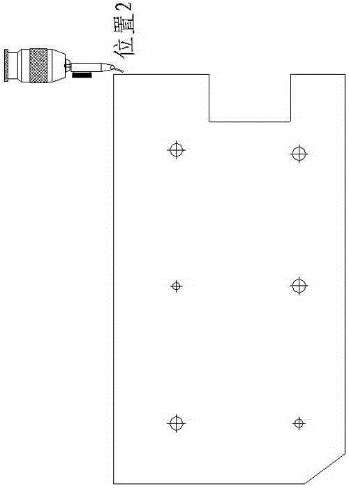
[0035] Figure 7 For the parts of the holes to be processed, 6 holes should be drilled and boring on a steel plate, and the starting points of the coordinates of the 6 holes are different corners.

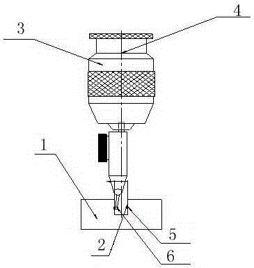
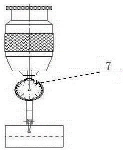
[0036] Step 1: According to the size of the part to be used, the processing equipment we choose is T4163 single-column vertical fine boring machine; the lever dial indicator is installed in the ER8 spring collet on the head of the BT50 tool holder, and the BT50 tool holder is installed in the main shaft of the equipment ;

[0037] Step 2: Fix the alignment block on the work surface of the equipment; move the main shaft of the equipment to position 1 near the alignment block (see Figure 7 ),

[0038] a. By lowering the spindle of the milling machine or boring machine, lower the head of the lever dial indicator to the middle of the slot with a slot width of 10mm ± 0.005mm, and when the head touches the busbar on the left side of the slot, the light is light within the range of 90°...


PUM


Abstract

The invention relates to the field of machining, in particular to a simple tool setting and alignment method for boring-milling machining. Through the alignment method, workers can carry out alignment and tool setting conveniently, accurately and rapidly before part machining. The method includes the steps that (1) according to the size of a part to be machined and the model of equipment, a spindle tool handle is selected, a lever indicator is arranged in an ER collet chuck of the head of the tool handle, and the tool handle is arranged in a spindle of a milling machine or a boring machine; (2) an alignment block is fixed to a working table top of the milling machine or the boring machine, after the angle of the head of the lever indicator is adjusted to be within the range from 30 degrees to 80 degrees, the head of the lever indicator is descended and placed in the middle of an alignment block groove, and circles are drawn on generatrices of the two sides of the middle of the alignment block groove repeatedly until the position where the head of the lever indicator displays the maximum value is found; and (3) a console of the milling machine or a console of the boring machine is operated, so that the lever indicator in the alignment block groove is lifted.

Description

technical field [0001] The invention relates to the field of mechanical processing, in particular to a simple tool setting and alignment method for boring and milling processing. Background technique [0002] The boring and milling process of mechanical parts has the problem of tool alignment. The usual method of alignment is to use a dial gauge to align the reference plane of the part, then install a milling cutter, mill a knife on the surface of the part with a small margin, and then proceed to subsequent processing after determining the coordinates; in addition, some workers will also use non-contact Type tool setting method, which uses a dial indicator to align the reference plane of the part, then installs the milling cutter, and inserts a plug between the surface of the part to be processed and the milling cutter until the plug is tightly fitted and cannot fall off. Determine the coordinates of the main axis of the part by subtracting the size of the plug, and then in...

Claims


Application Information

Patent Timeline
Patent Type & Authority Applications(China)
IPC IPC(8): B23Q15/22
CPCB23Q15/22
Inventor 张光伟赵养智魏广生
Owner 西安西航集团莱特航空制造技术有限公司
Why Eureka
Try Eureka