
Magnetic steel replacer

A changer and magnet technology, applied in the direction of laying tracks, roads, tracks, etc., can solve the problems of only replacement, difficult joint management, coordination and coordination, etc., to save material costs, save magnetic materials, and shorten construction. effect of time

Active Publication Date: 2016-01-06
青岛瑞铁电工科技有限公司
View PDF6 Cites 1 Cited by
  • Summary
  • Abstract
  • Description
  • Claims
  • Application Information

AI Technical Summary

Problems solved by technology

So far, the replacement of the under-passing magnet still adopts the method of replacing the entire magnet, and the problems of only replacing the magnet and difficult management of the joint have not been solved.
[0006] In short, the above two methods have many defects such as difficulty in multi-department cooperation and coordination, time-consuming and laborious, waste of resources, and high cost.

Method used


Image

  • Magnetic steel replacer
  • Magnetic steel replacer
  • Magnetic steel replacer

Examples


Embodiment 1

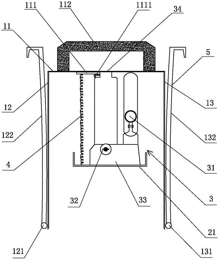
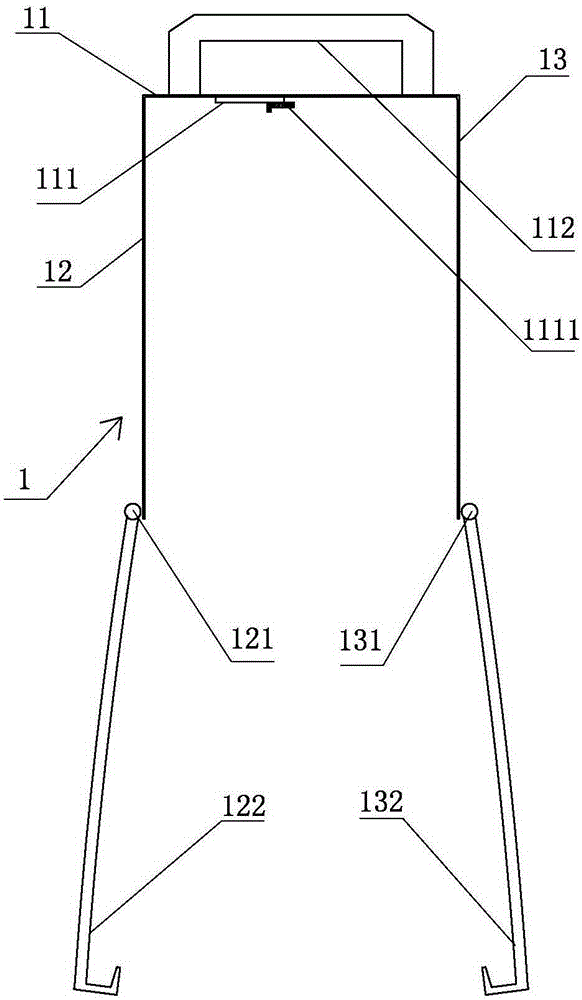
[0027] Such as figure 1 , 2 , 3, a magnetic steel changer, including a "Π"-shaped frame 1 and an "H"-shaped bracket 2 sleeved in it, the "Π"-shaped frame 1 is composed of a top plate 11 and the left and right sides connected to it. Side plate 12, right side plate 13 are made up of, and the outer surface of left side plate 12, right side plate 13 bottoms, respectively horizontally, vertically arrange left rotating shaft 121, right rotating shaft 131, left pull hook is respectively installed on left rotating shaft 121, right rotating shaft 131 122. The right pull hook 132, the left pull hook 122, and the right pull hook 132 can rotate up and down around the left rotating shaft 121 and the right rotating shaft 131;

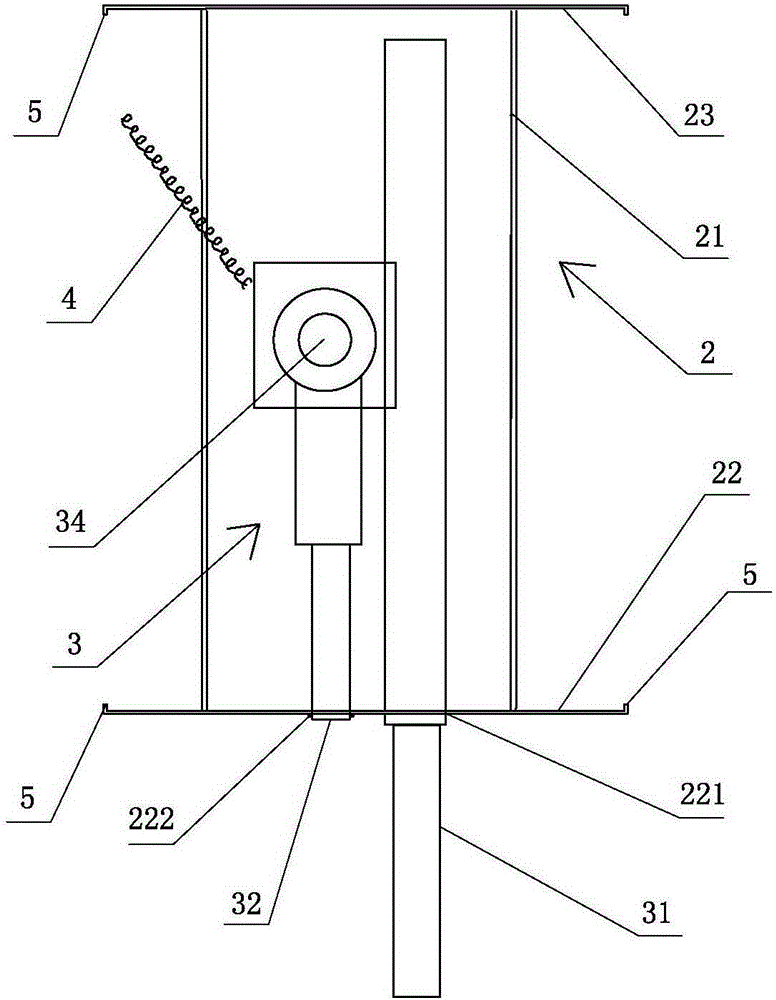
[0028] The "H"-shaped support 2 is composed of a central horizontal plate 21 and its front and rear side plates 22 and rear side plates 23; Movement; the jack 3 includes an operating handle 31, an oil return valve knob 32, a base 33, and a top cover 34, and the bas...


PUM


Abstract

The invention discloses a magnetic steel replacer, and belongs to the technical field of train operation auxiliary equipment. The magnetic steel replacer comprises a II-type sleeve frame and an H-type support, the II-type sleeve frame is formed by connecting a left side plate and a right side plate through a top plate, and the H-type support is formed by connecting a front side plate and a rear side plate through a middle cross plate. The support is sleeved with the sleeve frame. A left rotary shaft is horizontally arranged on the outer surface of the lower portion of the left side plate, and a right rotary shaft is longitudinally arranged on the outer surface of the lower portion of the right side plate. A left pull hook and a right pull hook are arranged on the left rotary shaft and the right rotary shaft respectively, and can vertically rotate around the left rotary shaft and the right rotary shaft. A lifting device is arranged on the middle cross plate of the support. The lifting device can drive the sleeve frame to do vertical reciprocating motion along the support. Compared with the prior art, the magnetic steel replacer has the advantages that construction personnel are greatly reduced, work time is greatly shortened, and work efficiency is improved; replacement is convenient and fast, operation is easy, and meanwhile a sleeper is not damaged, and can continue to be used; magnetic steel is protected, and can be recycled to be reused; resources are greatly saved, and cost is reduced.

Description

technical field [0001] The invention belongs to the technical field of train operation auxiliary equipment, and in particular relates to a magnetic steel changer. Background technique [0002] The ground magnetic sensor for automatic phase separation of electric locomotives is the ground magnetic equipment of the on-board automatic phase separation control system based on maintenance-free ground positioning technology. When the electric locomotive passes by, the ground magnetic sensor embedded in the ground will send a corresponding signal to the locomotive, and then through the on-board induction receiver and the over-phase control device, the electric locomotive will automatically complete the power-off and over-phase, so as to ensure the automatic over-phase Safe and reliable. At present, the electromagnetic sleeper installed on the ballasted track is to open a trapezoidal groove at one end of the type III concrete sleeper, install a fixed magnetic steel in the groove, p...

Claims


Application Information

Patent Timeline
Patent Type & Authority Applications(China)
IPC IPC(8): E01B29/06
Inventor 苑新江陈守剑
Owner 青岛瑞铁电工科技有限公司
Learn More