Universal damping device

A kind of universal damping, together technology, applied in the direction of bridge parts, building components, bridges, etc., can solve the problem of a single damping device, can not be well adapted to earthquakes, etc., to achieve reasonable mechanical design, good energy dissipation capacity and structural performance, The effect of convenient construction

Inactive Publication Date: 2016-01-06
TSINGHUA UNIV
View PDF4 Cites 11 Cited by
  • Summary
  • Abstract
  • Description
  • Claims
  • Application Information

AI Technical Summary

Problems solved by technology

At present, whether it is a velocity-type damping device or a displacement-type damping device, the damping device that is effective in a single direction is still

Method used


Image

  • Universal damping device
  • Universal damping device
  • Universal damping device

Examples


Embodiment 1

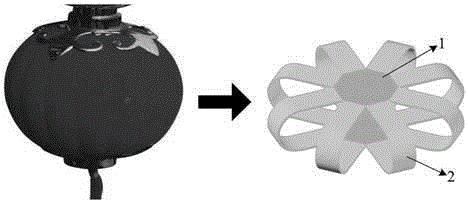
[0033] The mimetic source of the present invention's "cage" type universal damping device 4 is the traditional lantern of my country ( Figure 10 ). The lantern-like "cage" system has an axisymmetric spatial structure and a good spatial deformation recovery ability, which can better meet the requirements of the universal effective damping device.

[0034] "cage" type universal damper 4 of the present invention, as figure 1 shown. It consists of two panels 1 and multiple limb panels 2. Panel 1 uses a polygonal steel plate, which can be a regular polygon. The limb panels 2 are lantern limbs mimicking U-shaped strips. The number of limb panels 2 corresponds to the number of sides of panel 1. Not less than three, preferably eight or more. The two panels 1 are fixedly connected to the two ends of the limb board 2 respectively. The connection method can be welding, full bolting or mixed bolting connection. In this embodiment, it is a welding connection.

[0035] The "cage" type u...

Embodiment 2

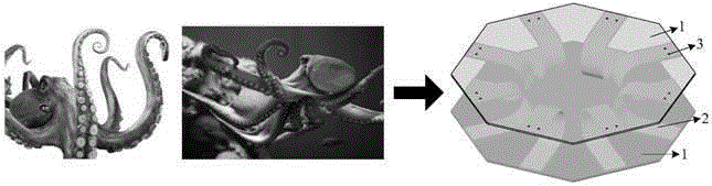
[0043] The imitation of the "chapter" type universal damping device of the present invention comes from the marine organism octopus ( Figure 11 ). The octopus-mimetic "chapter" system has an axisymmetric spatial structure, better spatial deformation recovery ability and better overall firmness, and can better ensure the universal and effective performance of the damping device.

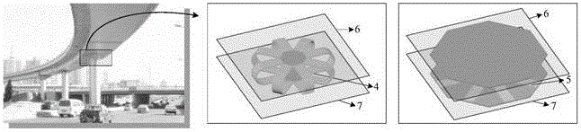
[0044] like Figures 5 to 7As shown, the "chapter" type universal damping device of the present invention is composed of a panel 1 and a plurality of limb panels 2. The panel 1 uses a polygonal or circular steel plate, which can be a regular polygon. The number of limb panels and the number of sides of the panel 1 Correspondingly, it should not be less than three, preferably eight or more. The panel 1 and the end of the limb board 2 are fixedly connected, and the connection method can be welding, full bolt connection or a mixed connection of bolt welding. In this embodiment, it is a full bolt connec...


PUM


Abstract

The invention discloses a universal damping device, relates to an energy dissipation damping device applied to building and bridge structures, particularly relates to energy dissipation support structures in the field of bridge engineering, and belongs to the technical field of structural engineering. The universal damping device comprises face plates and more than three leg plates. The face plates are geometrically circular or polygonal or can be geometrically in the shapes of regular polygons; the leg plates are geometrically in the shapes of U-shaped strips, and the appropriate quantity of the leg plates is equal to or larger than eight. The universal damping device has the advantages that the universal damping device is used for lateral force resisting systems of building and bridge structures and can be particularly used as a beam-bottom energy dissipation support for bridge structures, accordingly, plastic zones formed at arc-shaped sections of the leg plates in main deformation directions under uncertain multi-directional effects still can be guaranteed under random seismic effects, and effective universal damping effects can be realized; the universal damping device can be adjusted to have different lateral rigidity degrees in different directions by means of strength designs; the universal damping device is flexible in structure and reasonable in stress and has excellent technical and economical benefits.

Description

technical field [0001] The invention relates to a universal damping device applied to buildings and bridge structures, and belongs to the technical field of structural engineering, in particular to a universal damping device for a beam bottom damping support of a bridge structure. Background technique [0002] After the Hanshin earthquake in Japan and the Northridge earthquake in the United States, various energy-consuming damping devices have been in-depth research and rapid promotion and application in Japan and the United States and other earthquake-prone developed countries. In our country, the research on energy-dissipating damping devices is in a stage of rapid development. my country is also an earthquake-prone country, affected by the circum-Pacific seismic belt and the Mediterranean-Himalayan seismic belt, earthquake disasters occur frequently. At the same time, with the rapid development of my country's economy and the continuous progress of society, various , Spec...

Claims


Application Information

Patent Timeline
IPC IPC(8): E04B1/98E01D19/04
Inventor 聂建国周萌
Owner TSINGHUA UNIV
Why Eureka
Try Eureka