
rotary internal combustion engine

An internal combustion engine, rotary technology, applied in the direction of internal combustion piston engines, combustion engines, mechanical equipment, etc., can solve the problems of pistons that cannot be cooled and effectively lubricated, difficult to burn, difficult to cool, etc., to solve the problems of unable to cool and effectively lubricate, improve Ignition and combustion performance, smooth running effect

Active Publication Date: 2019-06-07
庞乐钧
View PDF1 Cites 0 Cited by
  • Summary
  • Abstract
  • Description
  • Claims
  • Application Information

AI Technical Summary

Problems solved by technology

[0002] Existing patent number: 200510072363.7 Rotary internal combustion engine, because it does not have a special combustion chamber, resulting in long ignition propagation distance, difficult combustion, incomplete combustion of the mixture, high fuel consumption, low thermal efficiency, and large emission pollution; the piston cannot be cooled and Effective lubrication, no effective lubrication between the cylinder block and piston ring, no effective sealing between the rotors, no reasonable and effective design scheme for the intake and exhaust ports, and no concrete implementation, unreasonable layout of the gearbox and difficult cooling

Method used


Image

  • rotary internal combustion engine
  • rotary internal combustion engine
  • rotary internal combustion engine

Examples


Embodiment approach 1

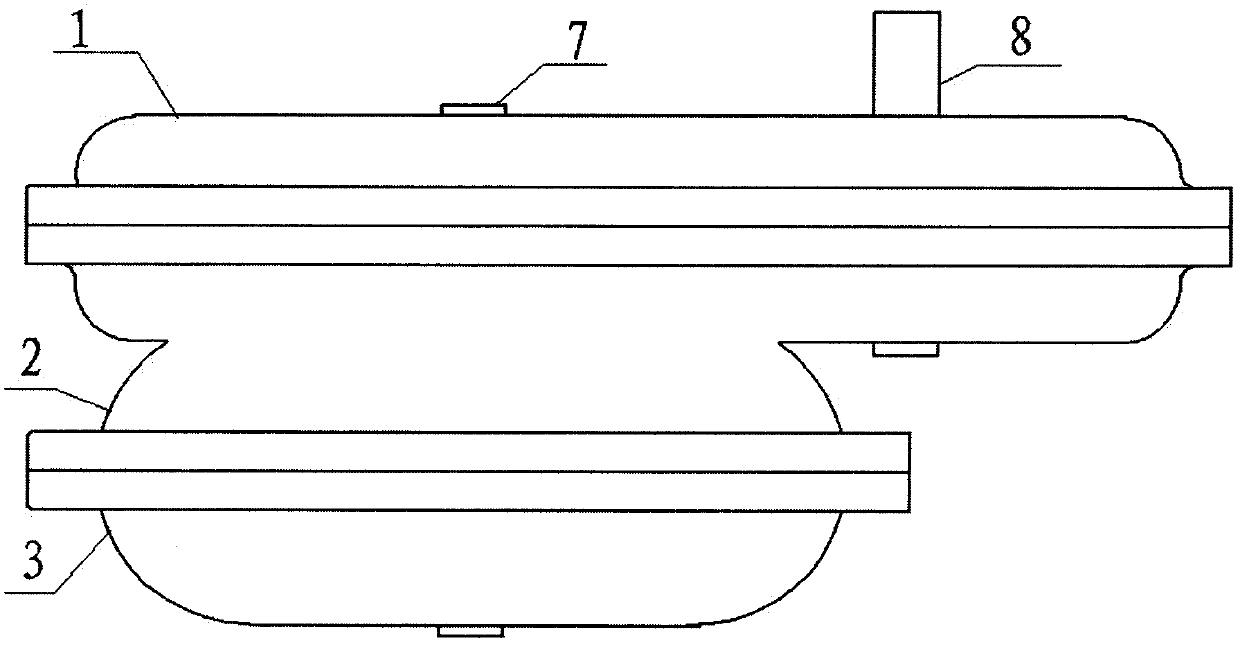
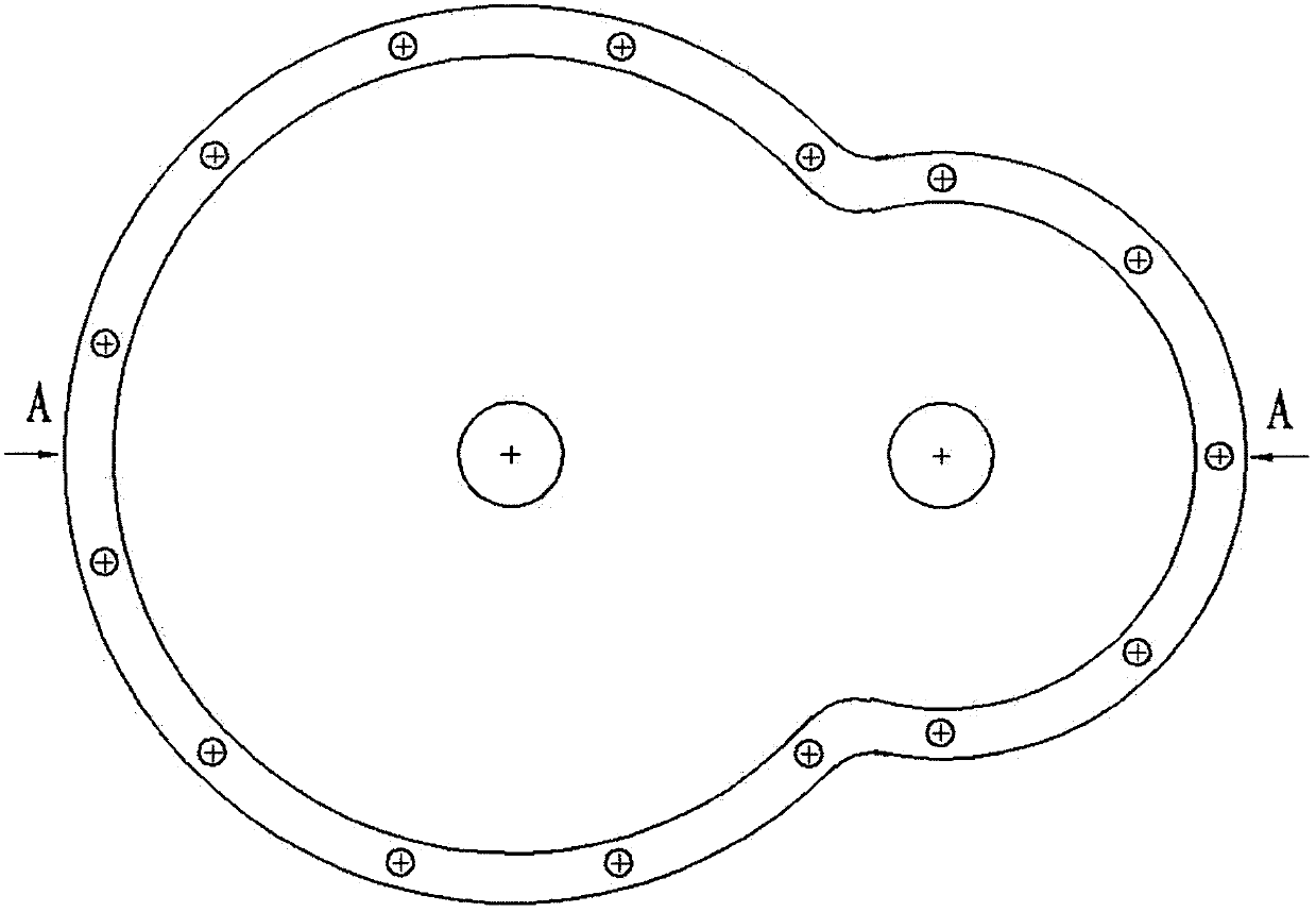
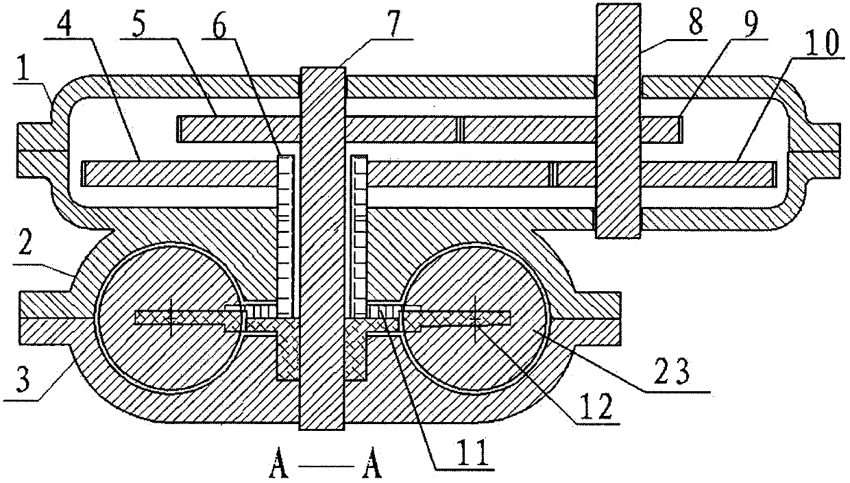
[0050] Implementation method 1: This structure includes a set of annular cylinders with circular cross-sections composed of two annular cylinders 2 and 3 with semicircular cross-sections, and the gear box is arranged on one side of the cylinders, such as figure 1 , 2 , 3, 4, 5, and 6; the cylinder body is provided with an oil passage 31 specially for the circulation of lubricating oil near the end of the air inlet 38, and the oil passage is sealed with a porous material 32, which can make the lubricating oil seep out. Ensure that the piston ring is effectively lubricated when the piston passes, such as Figure 7 , 8 As shown, the arrow in the figure is the flow diagram of lubricating oil; the intake hole 38 and the exhaust hole 39 on the cylinder block are all strip-shaped, and the strip shape of the intake and exhaust holes is arranged according to the forward direction of the piston rotation One end of the intake and exhaust holes in the forward direction of the piston is ...

Embodiment approach 2

[0051] Implementation method 2: two identical, independent gearboxes 42 and 43 that are completely separated from the cylinder except where there are shaft holes are provided; two identical annular cylinders with a semicircular section are provided 35, 40, forming a set of circular cylinder with circular section; two rotor shafts 13, 16 are installed on the two rotors respectively, and two non-circular gears 4, 5 are respectively installed in two independent gear boxes, Mesh respectively with two eccentric gears 9,10 installed on the same power output shaft 41, as Figure 35 , 36 , 37; Such setting is more conducive to the cooling of the cylinder block and the setting of the intake and exhaust holes, and the assembly of other supporting facilities; except that the above feature setting, other are all the same as the implementation method one.

[0052] The working principle of this structure is as follows: it uses the difference in rotation angle between the two eccentric gear...


PUM


Abstract

The invention provides a rotary internal combustion engine. The rotary internal combustion engine is characterized in that a cylinder block is provided with an oil channel specially used for lubricating piston rings; an air inlet and an air outlet of the rotary internal combustion engine are both in a long strip shape; rotors of the rotary internal combustion engine are provided with sealing rings and sealing blocks used for sealing between the rotors, and the rear faces of the sealing rings and the rear faces of the sealing blocks are both provided with springs; pistons of the rotary internal combustion engine are provided with special combustion chambers and further provided with channels used for circulation of cooling liquid, and the piston rings made of porous materials are installed on the channels; the piston rings specially used for the annular cylinder block and provided with certain notches are further arranged. All gears are arranged in the same gearbox.

Description

technical field [0001] The invention relates to an internal combustion engine, especially a rotary internal combustion engine. technical background [0002] Existing patent number: 200510072363.7 Rotary internal combustion engine, because it does not have a special combustion chamber, resulting in long ignition propagation distance, difficult combustion, incomplete combustion of the mixture, high fuel consumption, low thermal efficiency, and large emission pollution; the piston cannot be cooled and Effective lubrication, effective lubrication cannot be carried out between the cylinder block and the piston ring, the rotors cannot be effectively sealed, there is no reasonable and effective design scheme for the intake and exhaust ports, and it cannot be implemented concretely. The layout of the gearbox is unreasonable and cooling is difficult. Contents of the invention [0003] The purpose of the present invention is to improve the gearbox structure, cylinder body mechanism,...

Claims


Application Information

Patent Timeline
Patent Type & Authority Patents(China)
IPC IPC(8): F02B53/00F02B55/08F02B53/04F02B55/02F02B55/04F02B55/14F02B61/06F02F5/00
CPCY02T10/12
Inventor 庞乐钧
Owner 庞乐钧
Learn More