
LED lamp with water-circulating heat dissipation function

A technology of LED lamps and water circulation, applied in the field of lighting, can solve the problems of waste heat dissipation, poor heat dissipation effect, etc., and achieve the effects of improving heat absorption efficiency, improving heat conduction effect, and improving uniformity

Active Publication Date: 2016-01-06
JIANGSU TIWIN OPTO ELECTRONICS TECH
View PDF14 Cites 4 Cited by
  • Summary
  • Abstract
  • Description
  • Claims
  • Application Information

AI Technical Summary

Problems solved by technology

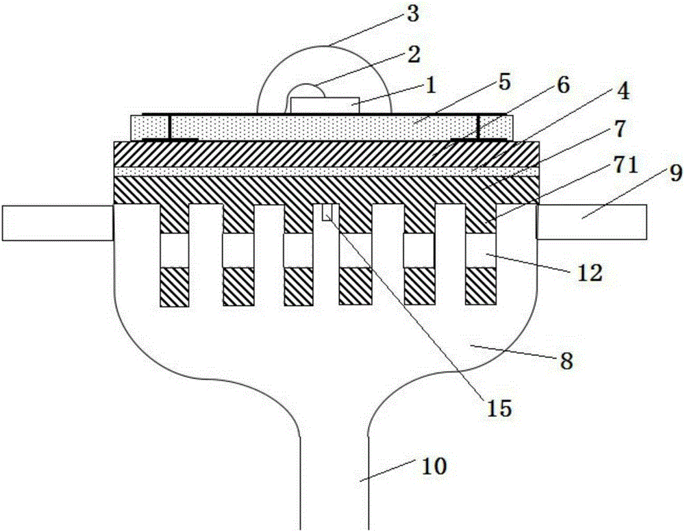
[0005] In order to overcome the problems of poor heat dissipation effect and waste of heat in the prior art, the present invention provides a water circulation heat dissipation LED lamp, including LED chips, connecting wires, lenses, LED chip substrates, system circuit boards, and heat sinks. The connecting wire connects the LED chip and the LED chip substrate, the LED chip, the LED chip substrate, the system circuit board and the heat sink are sequentially connected from top to bottom, and the lens is fixed on the LED chip substrate Above, the LED chip is packaged in the inner space formed by the lens and the LED chip substrate, a heat dissipation device for heat dissipation is provided under the heat sink, and the water inlet of the heat dissipation device is located directly below the heat dissipation device. The heat sink is provided with more than two water outlets, and the water outlets are evenly distributed on the side of the heat sink

Method used


Image

  • LED lamp with water-circulating heat dissipation function
  • LED lamp with water-circulating heat dissipation function
  • LED lamp with water-circulating heat dissipation function

Examples


Embodiment Construction

[0029] The present invention will be described in further detail below in conjunction with the examples. It should be understood that the specific embodiments described here are only used to explain the present invention, not to limit the present invention.

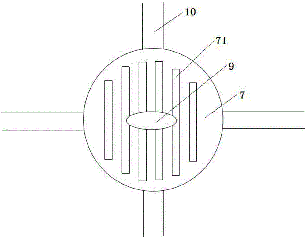
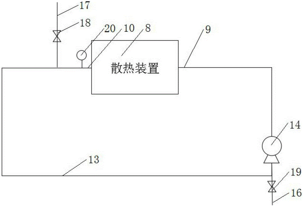
[0030] Such as Figure 1-2 Shown are the preferred front sectional view and bottom view of the present invention, including LED chip 1, connecting wire 2, lens 3, LED chip substrate 5, system circuit board 6, heat sink 7, connecting wire 2 connecting LED chip 1 and LED chip The substrate 5, the LED chip 1, the LED chip substrate 5, the system circuit board 6 and the heat sink 7 are sequentially connected from top to bottom, the lens 3 is fixed on the LED chip substrate 5, and the LED chip 1 is packaged on the lens 3 and the LED chip substrate 5. In the inner space formed, a heat dissipation device 8 for heat dissipation is provided below the heat sink 7, and the water inlet 9 of the heat dissipation device 8 is located d...


PUM


Abstract

The invention discloses an LED lamp with a water-circulating heat dissipation function. The LED lamp comprises an LED wafer (1), a connecting wire (2), a lens (3), an LED wafer substrate (5), a system circuit board (6) and a heat dissipation fin (7), wherein a heat dissipation device (8) used for heat dissipation is arranged below the heat dissipation fin (7); the water inlet (9) of the heat dissipation device (8) is positioned under the heat dissipation device (8); and two or more water outlets (10) are arranged the heat dissipation device (8) and uniformly distributed on the side surface of the heat dissipation device (8). The LED lamp has the beneficial effects that the water inlet is arranged under the heat dissipation device and the water outlets are arranged on the side surface of the heat dissipation device, and water flows in from below and flows out from the surroundings, so that water flow of relative low temperature is formed from the middle to both sides of the heat dissipation fin, heat on the heat dissipation fin is brought away, uniform heat absorption of the water flow is achieved, heat absorption efficiency of the water flow is improved, and all regions of the heat dissipation fin can keep the same and stable temperature.

Description

technical field [0001] The invention relates to the lighting field, in particular to a water circulation heat dissipation LED lamp. Background technique [0002] As a new generation of lighting source, LED has the advantages of long operating life, low power consumption, high brightness and small size compared with traditional light sources, so it has attracted more and more attention. LED chips are developing towards small size and high power, but their luminous efficiency is currently only 10%-20%, that is to say, as high as 80%-90% of electric energy is directly converted into heat. At present, the chip size of high-power LED (power > 1W) used in lighting is mostly above 1mm×1mm, and the heat flux exceeds 100W / cm. If the heat of the chip cannot be dissipated in time, the high junction temperature of the chip will reduce its luminescence. Efficiency and reliability will cause the chip to age or even fail, which is an important bottleneck restricting the development of ...

Claims


Application Information

Patent Timeline
IPC IPC(8): F21S2/00F21V29/89F21V29/83F21V29/71F21V29/56F21Y101/02
CPCF21S2/00
Inventor 严圣军
Owner JIANGSU TIWIN OPTO ELECTRONICS TECH
Learn More