Multi-wire array-laser three-dimensional scanning system and multi-wire array-laser three-dimensional scanning method

A laser 3D and scanning system technology, applied in the field of 3D scanning of object surface geometry, can solve the problems of large data noise, reduced accuracy, and difficult to accurately control the working distance, and achieve high reliability.

Active Publication Date: 2016-01-06
BEIJING TENYOUN 3D TECH CO LTD
View PDF5 Cites 34 Cited by
  • Summary
  • Abstract
  • Description
  • Claims
  • Application Information

AI Technical Summary

Problems solved by technology

The traditional marker point splicing technology has the problem of high false splicing rate. The performance is that the data of multiple scans is ambiguous when they are uniformly registered to the same coordinate system, which leads to the fact that a certain piece of scanned data is separated from the overall data and generates an incorrect model.
This problem can be solved by manually deleting after each single-sided scan in white light 3D scanning, but it cannot be solved by similar methods in laser 3D scanning in continuous scanning mode, so rescanning is usually required after misalignment , which greatly af

Method used


Image

  • Multi-wire array-laser three-dimensional scanning system and multi-wire array-laser three-dimensional scanning method
  • Multi-wire array-laser three-dimensional scanning system and multi-wire array-laser three-dimensional scanning method
  • Multi-wire array-laser three-dimensional scanning system and multi-wire array-laser three-dimensional scanning method

Examples


Embodiment Construction

[0047] The following will clearly and completely describe the technical solutions in the embodiments of the present invention with reference to the accompanying drawings in the embodiments of the present invention. Obviously, the described embodiments are only some, not all, embodiments of the present invention. Based on the embodiments of the present invention, all other embodiments obtained by persons of ordinary skill in the art without making creative efforts belong to the protection scope of the present invention.

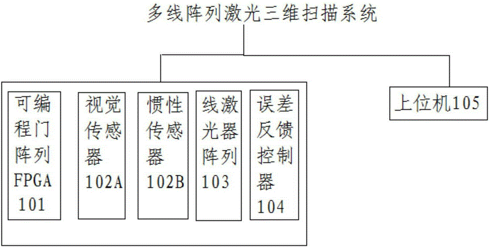
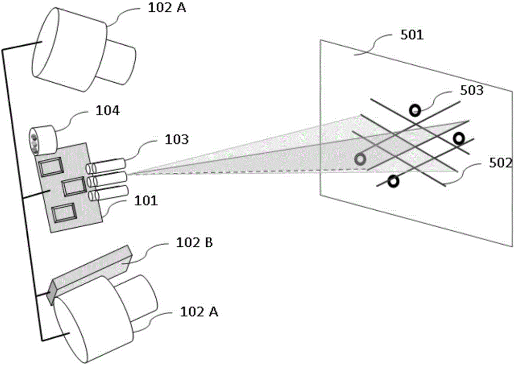
[0048] First, the multi-line array laser three-dimensional scanning system in this application is described as follows: figure 1 As shown, the multi-line array laser three-dimensional scanning system includes a programmable gate array FPGA, at least one stereoscopic image sensor, an inertial sensor, a line laser array, an error feedback controller and a host computer, which can be understood as a control device , for example: upper computer. It has the functi...


PUM


Abstract

The invention provides a multi-wire array-laser three-dimensional scanning system and a multi-wire array-laser three-dimensional scanning method. In the system, through a programmable gate array FPGA, accurate synchronization and logic control of the multi-wire array-laser three-dimensional scanning system can be realized. A wire laser array is used as a projection pattern light source. Through the FPGA, trigger signals are sent to a stereo vision image sensor, an inertial sensor and the wire laser array. An upper computer receives an image pair shot by the stereo vision image sensor, and carries out coding, decoding and three-dimensional reconstruction on a laser wire array pattern in the image pair. The three-dimensional reconstruction and three-dimensional characteristic point matching and aligning are performed on a characteristic point of a measured object surface. A mixing sensing positioning technology is used to carry out prediction and error correction on matching calculation, which is used for registration and splicing of time-domain-laser three-dimensional scanning data. Simultaneously, measurement error grade assessment is performed in real time and an assessment result is fed back to an error feedback controller so that an adjusting indication is obtained. Therefore, laser three-dimensional scanning with low cost, high efficiency, high reliability and high precision is realized.

Description

technical field [0001] The invention relates to the technical field of three-dimensional scanning of object surface geometry, in particular to a multi-line array laser three-dimensional scanning system and a multi-line array laser three-dimensional scanning method. Background technique [0002] In recent years, 3D scanning, as a fast 3D digital technology, has been increasingly used in various fields, including reverse engineering, industrial inspection, computer vision, CG production, etc., especially in the current rapidly developing 3D printing and intelligent manufacturing. In the field of 3D scanning, as a front-end 3D digitization and 3D visual sensing technology, it has become an important part of the industry chain; at the same time, various applications have raised the bar in many aspects such as the cost, practicability, accuracy and reliability of 3D scanning equipment. higher requirement. [0003] Optical 3D scanning is the most common modern technical means in ...

Claims


Application Information

Patent Timeline
IPC IPC(8): G01B11/25
CPCG01B11/2545G01B2210/52G01B5/25G01C19/00G01D21/02G05B6/02H04N23/45G01B11/2513G01B11/2518G01B11/25G01B11/2522
Inventor 杜华李仁举叶成蔚
Owner BEIJING TENYOUN 3D TECH CO LTD
Why Eureka
Try Eureka