Bracing wire suppression vibration device

A technology for suppressing vibration and tension device, applied in the field of wind tunnel test, it can solve the problems of increasing the risk of the test, affecting the accuracy of aerodynamic data, difficult to accurately obtain the maximum lift coefficient, stall angle of attack, etc., so as to reduce the test risk and suppress the model Vibration, the effect of improving reliability

Active Publication Date: 2016-01-06
LOW SPEED AERODYNAMIC INST OF CHINESE AERODYNAMIC RES & DEV CENT
View PDF4 Cites 8 Cited by
  • Summary
  • Abstract
  • Description
  • Claims
  • Application Information

AI Technical Summary

Problems solved by technology

This situation is especially serious in the landing state or high wind speed, which directly affects the accuracy of aerodynamic data near the stall angle of attack, making it difficult to accurately obtain the maximum lift coef

Method used


Image

  • Bracing wire suppression vibration device

Examples


Embodiment 1

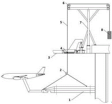
[0037] The present invention uses weights to pull steel cables to offset the reaction force on the aircraft model. The present invention sets a bracket on the outer wall of the top of the wind tunnel, and the upper end of the bracket is a horizontal horizontal frame. The pulley and the fixed pulley are respectively arranged on the two edges of the horizontal frame. A steel cable A is used. One end of the steel cable A is connected to the weight. The guide steel sleeve is then connected to the pole. In order to ensure the uniformity of the force on the steel cable A, it is necessary to set a movable pulley on the steel cable A. The movable pulley is set in the wind tunnel on the steel cable A, and a steel cable B is connected to the movable pulley. , and the other end of cable B is connected to the cantilever. In order to neutralize the force on the aircraft model more evenly, two steel cables A are set. The two steel cables A are connected to a point on the pole, and then the...

Embodiment 2

[0039] On the basis of Embodiment 1, remove the weight at the end of steel cable A, use an automatic tension device, connect steel cable A to the automatic tension device, collect the force on steel cable A through the control system, and then control the automatic tension device Stretching or loosening is performed to change the force exerted by steel cable A on the pole. The automatic tension device can adopt an electronic spring or an electromagnet to control the force exerted by the steel cable A on the pole by changing the force.

Embodiment 3

[0041] On the basis of Embodiment 1, the steel cable B can be disconnected from the cantilever, and then an automatic rope reel is set on the cantilever, the steel cable B is connected to the automatic rope reel, and the automatic rope reel is controlled by the control system to work The length of the steel cable B can be realized so that the force of the steel cable A changes through the action of the movable pulley, and the force exerted by the steel cable A on the pole can be controlled.


PUM


Abstract

The invention discloses a bracing wire suppression vibration device. The bracing wire suppression vibration device includes a stand positioned on the outer wall of the top of a wind tunnel, a stand column positioned in the wind tunnel, and a cantilever perpendicularly connected to the stand column and positioned in the wind tunnel; one end of the cantilever is connected to a fulcrum bar supporting a model; one end of a steel cable A is fixedly connected to the fulcrum bar connected to the cantilever, and the other end of the steel cable A passes through a movable pulley in the wind tunnel, then passes through the top of the wind tunnel and a fixed pulley on the fulcrum bar, and is connected to a weight; the movable pulley is fixedly connected to a steel cable B, and one end of the steel cable B is fixedly connected to the cantilever. The bracing wire suppression vibration device can change an inherent frequency of a system by increasing or decreasing weight so as to effectively avoid a resonance region, and meanwhile, the load of a super attack angle support system is reduced. Frictional resistance between a bracing wire and the pulleys plays a damping effect to suppress vibration.

Description

technical field [0001] The invention relates to the field of wind tunnel tests, in particular to a tensioning wire vibration suppression device. Background technique [0002] The wind tunnel test is an indispensable part of the aircraft development work. The aerodynamic data of the aircraft under different airflow conditions can be obtained through the wind tunnel test to provide data support for the flight test finalization of the aircraft. When an aircraft is being tested in a wind tunnel, it is usually scaled into a model according to a certain ratio, and it is supported by a supporting device. The supporting device also plays a role in controlling the change of the attitude angle of the model. At present, the wind tunnel test technology has been developed for a long time. For different types of models, technicians have developed corresponding test equipment for testing. Usually, the model used in the test is generally small, and the support rigidity is sufficient, so th...

Claims


Application Information

Patent Timeline
IPC IPC(8): G01M9/04
Inventor 许可段雪峰章荣平高大鹏陈洪梁鉴王芝春
Owner LOW SPEED AERODYNAMIC INST OF CHINESE AERODYNAMIC RES & DEV CENT
Why Eureka
Try Eureka