Vehicle driving deviated-track automatic measuring system based on laser scanning

A technology of laser scanning and automatic measurement, which is applied in vehicle testing, measuring devices, testing of machine/structural components, etc. It can solve problems such as inability to meet production requirements, complex equipment calibration and troublesome equipment installation for close-range camera detection methods

Inactive Publication Date: 2016-01-06
WUHAN UNIV OF SCI & TECH
View PDF4 Cites 11 Cited by
  • Summary
  • Abstract
  • Description
  • Claims
  • Application Information

AI Technical Summary

Problems solved by technology

The traditional vehicle deviation detection method is mainly the sprinkler positioning method, which has low detection accuracy and work efficiency, is easily affected by human and external environmental factors, and cannot meet production requirements
With the introduction of new technologies, modern deviation detection methods have appeared one after another, such as optical fiber sensor measurement method, GPS tracking measurement method, close-range camera detection method, laser ranging measurement method, etc., but these methods have their own defects. The sensory measurement method cannot be popularized and applied due to its relatively high cost. At the same time, the sensor needs to be buried in the ground before the measurement, which brings great trouble to the late

Method used


Image

  • Vehicle driving deviated-track automatic measuring system based on laser scanning
  • Vehicle driving deviated-track automatic measuring system based on laser scanning
  • Vehicle driving deviated-track automatic measuring system based on laser scanning

Examples


Example Embodiment

[0049] Example 1

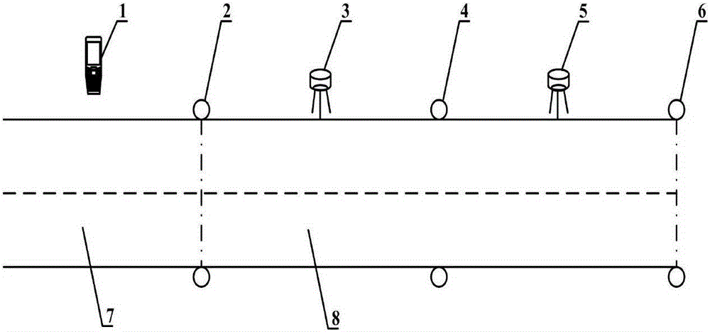
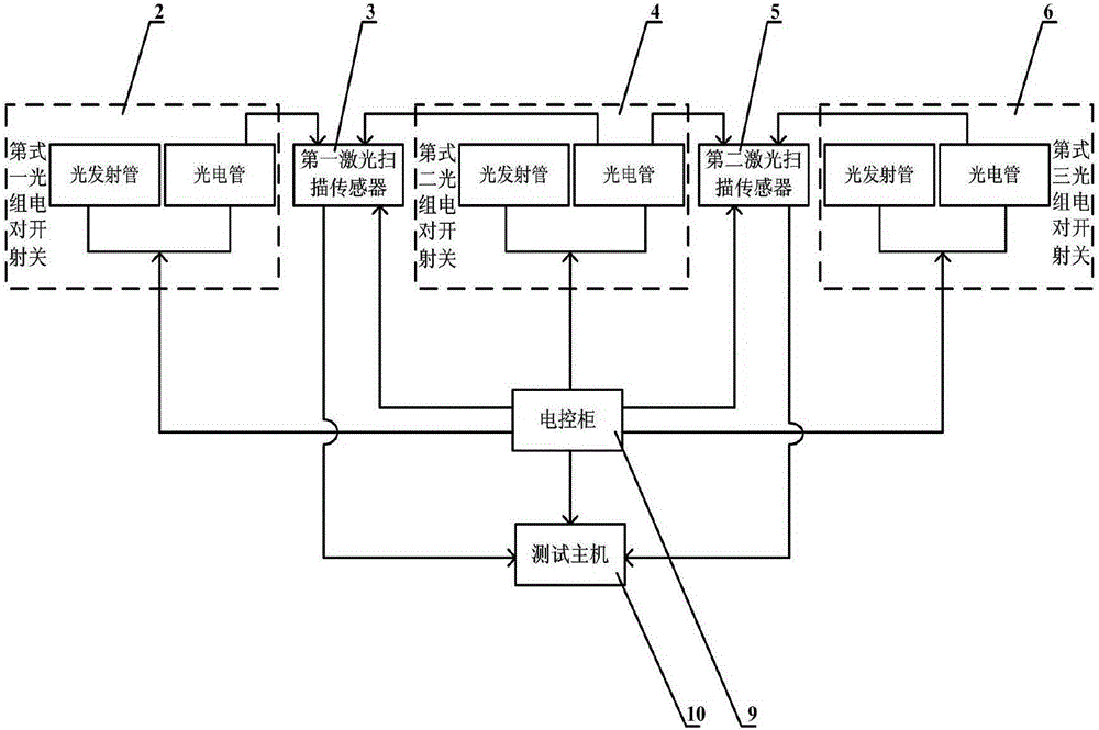
[0050] An automatic measurement system for vehicle running deviation track based on laser scanning. like figure 1 As shown, the automatic measurement system includes a mobile display terminal (1), a first group of beam-type photoelectric switches (2), a first laser scanning sensor (3), a second group of beam-type photoelectric switches (4), a first group of beam-type photoelectric switches (4), Two laser scanning sensors (5), a third group of opposite-beam photoelectric switches, an electric control cabinet (9), a test host (10), a test preparation area (7) and a test area (8).

[0051] like figure 1 As shown, the starting point of the test area (8) is equipped with a first group of beam-type photoelectric switches (2), and a second group of beam-type photoelectric switches (2) are installed at the intermediate position between the start point of the test area (8) and the end point of the test area (8). The switch (4), the end point of the test area (8) i...


PUM


Abstract

The invention relates to a vehicle driving deviated-track automatic measuring system based on laser scanning. According to the technical scheme, identical opposite-type photoelectric switch sets are respectively arranged a start point, a middle point and an end point of a test area (8), and a light emitting tube and a photoelectric tube of each set of opposite-type photoelectric switches are arranged on two sides of the test area (8). A laser scanning sensor is arranged on the middle position between the middle set of opposite-type photoelectric switches and one adjacent set of opposite-type photoelectric switches. Each set of photoelectric tubes are connected with the adjacent laser scanning sensor through signal wires. The two laser scanning sensors are connected with corresponding interfaces of a test host (10) through data wires. A mobile display terminal (1) is connected with the test host (10) through a wireless local area network. The test host (10) is provided with vehicle driving deviation automatic detection and processing software. The vehicle driving deviated-track automatic measuring system has the advantages that all-weather real-time measurement is available, the precision is high, the automation degree is high, the measuring efficiency is high, the structure is simple, and the mounting and the dismounting are convenient.

Description

technical field [0001] The invention belongs to the technical field of automatic measurement of vehicle running deviation track. Specifically, it relates to an automatic measurement system for vehicle running deviation track based on laser scanning. Background technique [0002] The vehicle drives in a straight line on a flat road. Under the premise of keeping the steering wheel still, the vehicle generally drives in a straight line. However, there are inevitably certain errors in the design, manufacture and assembly process of the vehicle. , causing the vehicle to appear inconsistent between the center line of the front and rear axle centers and the center line of the driving track, that is, the deviation. The deviation of the vehicle can easily cause tire wear, and even lead to dangerous situations such as tire blowout and vehicle loss of control. Therefore, it is particularly important to measure the deviation of the vehicle. [0003] So far, there are many ways to test...

Claims


Application Information

Patent Timeline
IPC IPC(8): G01M17/007
Inventor 周兴林吕文莎伍洋郭剑波赵显新
Owner WUHAN UNIV OF SCI & TECH
Why Eureka
Try Eureka