Power supply for function debugging of UPFC converter valve and controlling method thereof

A converter valve and power supply technology, which is applied in power transmission AC network, inverter equipment with reversible, etc., can solve the problems of lack of MMC sub-module, complicated wiring, and wrong wiring, so as to improve safety and reliability. , to avoid wiring errors, to prevent the effect of short-circuit burning

Inactive Publication Date: 2016-01-06
STATE GRID CORP OF CHINA +2
View PDF5 Cites 2 Cited by
  • Summary
  • Abstract
  • Description
  • Claims
  • Application Information

AI Technical Summary

Problems solved by technology

[0005] The purpose of the present invention is to overcome the deficiencies in the prior art, provide a power supply for UPFC converter valve function debugging, and solve the problem that the project site does not have the condition of separately applying a DC power supply to the MMC sub-module, resulting in complicated wiring and power consumption during the debugging process. The length of time and the technical problems of wiring errors are prone to occur during the debugging process

Method used


Image

  • Power supply for function debugging of UPFC converter valve and controlling method thereof

Examples


Embodiment Construction

[0018] The present invention will be further described below in conjunction with the accompanying drawings. The following examples are only used to illustrate the technical solution of the present invention more clearly, but not to limit the protection scope of the present invention.

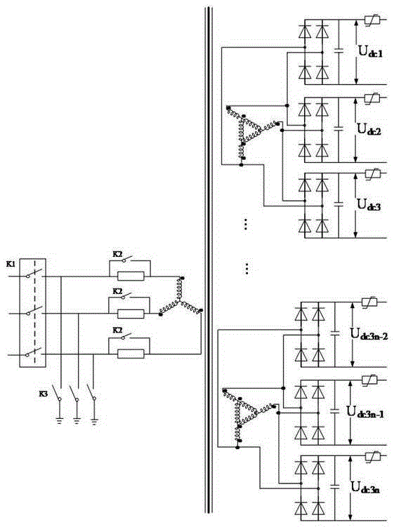
[0019] Such as figure 1 Shown is the circuit diagram of the power supply for UPFC converter valve function debugging provided by the present invention, including a transformer, a current-limiting resistor connected in series on each phase of the primary side of the transformer, and a bypass switch connected in parallel at both ends of the current-limiting resistor. The connection node between the current limiting resistor and the main circuit breaker is also grounded through a series grounding switch. The main circuit breaker adopts a three-phase AC circuit breaker, which is connected between the power supply and the current limiting resistor, and the power supply can be 380V AC.

[0020] The...


PUM


Abstract

The invention discloses a power supply for function debugging of a UPFC converter valve and a controlling method thereof. The power supply comprises a transformer; a primary side of the transformer is connected in series with a current-limiting resistor and a main circuit breaker and then is connected with a power source unit; and by-pass switches are connected in parallel to the two ends of the current-limiting resistor. Grounding switches are connected in series between connection nodes of the current-limiting resistor and the main circuit breaker. A plurality of secondary sides are arranged at the transformer, wherein the number of the secondary sides is not less than the number of to-be-debugged UPFC converter valves; a single-phase rectification bridge is connected between any two phases of each secondary side; and an output terminal of the single-phase rectification bridge is connected in parallel with a filter capacitor. In addition, the invention also discloses a controlling method of a power supply for function debugging of a UPFC converter valve. Before usage, the main circuit breaker is turned off and the by-pass switches are in an off state; first-stage charging is carried out on the filter capacitor; when the output terminal voltage of the single-phase rectification bridge reaches over 400V, the by-pass switches are turned off; and second-stage charging is carried out on the filter capacitor. With the power supply, a phenomenon that the converter valve is damaged due to an impact current can be avoided.

Description

Technical field [0001] The present invention involves a power supply for the functional debugging of the UPFC flow valve, and also involves a control method for the power supply for the function debugging of the UPFC flow valve, which is the field of power technology. Background technique [0002] With the expansion of power system installed capacity and power demand, the interconnection between distributed grids has become increasingly urgent.Although the power grid connection can achieve mutual benefits of electricity and dynamic power, the grid interconnection will also cause a series of problems in terms of security stability and trend control in the power grid.At present, dynamic stability has become a bottleneck of the safety and stability of the power system. In recent years, new problems have generally occurred in major power grids in the field of dynamic stability.Smart grid is an interactive system that requires the power grid to have high adaptation and response capabi...

Claims


Application Information

Patent Timeline
Patent Type & Authority Applications(China)
IPC IPC(8): H02M7/70H02J3/36
CPCY02E60/60
Inventor 史明明费骏韬袁晓冬陈兵方鑫罗珊珊刘俊
Owner STATE GRID CORP OF CHINA
Why Eureka
Try Eureka