
High-precision real-time signal filter

A filter, high-precision technology, applied in impedance networks, digital technology networks, electrical components, etc., can solve the problems of complex filter circuit structure, complex function, low precision, etc., to reduce the mode conversion process, high filtering accuracy, guaranteeing Undistorted effect

Active Publication Date: 2016-01-06
LOW SPEED AERODYNAMIC INST OF CHINESE AERODYNAMIC RES & DEV CENT
View PDF5 Cites 4 Cited by
  • Summary
  • Abstract
  • Description
  • Claims
  • Application Information

AI Technical Summary

Problems solved by technology

Most of the existing filter circuits are complex in structure, complex in function, low in precision, and do not have the function of real-time signal processing. However, in the application of on-site acquisition and processing of rotating equipment, the filter is required to have high precision, no attenuation in the passband, and no attenuation in the transition band. As steep as possible, large stopband attenuation, and at the same time have real-time functions

Method used


Image

  • High-precision real-time signal filter
  • High-precision real-time signal filter
  • High-precision real-time signal filter

Examples


Embodiment Construction

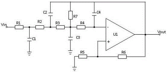
[0032] Such as figure 1 As shown, it is the analog filtering part in the present invention, including a low-noise high-precision operational amplifier OP177, and the signal input terminal Vin is connected to the precision operational amplifier through the first resistor R1, the second resistor R2, the third resistor R3 and the fourth resistor R4. The inverting input terminal of the precision operational amplifier is connected to the fifth resistor R5 between the non-inverting input terminal of the precision operational amplifier and the ground, and the sixth resistor R6 is connected between the non-inverting input terminal of the precision operational amplifier and the output terminal of the operational amplifier. The connection between the resistor R1 and the second resistor R2 is grounded through the first capacitor C1, the connection between the second resistor R2 and the third resistor R3 and the output terminal of the operational amplifier is connected to the second capaci...


PUM


Abstract

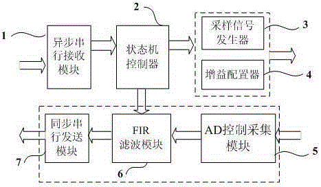
The invention discloses a high-precision real-time signal filter. An analog filter circuit, an analog to digital conversion circuit and a digital filter circuit are serially connected between signal input and signal output in sequence; the analog filter circuit outputs signals with frequency lower than 800HZ; and the digital circuit outputs signals with frequency lower than 100HZ. According to the high-precision real-time signal filter disclosed by the invention, by means of an FPGA chip design, a filtering parameter can be adjusted in a real time manner by receiving an external signal instruction, the filtering of the entire circuit is controlled, and compared with the single frequency band filtering mode of a traditional filter, the high-precision real-time signal filter disclosed by the invention has better practicability; moreover, since software control is adopted, the filtering precision can be higher and more reliable by means of a compensation function of a chip design circuit, and output signals are more stable; and furthermore, the filter disclosed by the invention directly inputs an analog signal and filters the analog signal to output a digital signal, and the output signal can be directly used and transmitted, so that a large amount of mode conversion processes are reduced, and non-distortion of the signal is ensured.

Description

technical field [0001] The invention relates to the field of data acquisition and processing, in particular to a high-precision signal real-time filter. Background technique [0002] The tiny signal acquisition of rotating equipment in a complex environment has strong electromagnetic interference and mechanical vibration electrical signal interference. The filter circuit is used to improve the accuracy of the signal. It is used to allow the signal components in a certain frequency range to pass, while suppressing the application of other frequency components. Most of the existing filter circuits are complex in structure, complex in function, low in precision, and do not have the function of real-time signal processing. However, in the application of on-site acquisition and processing of rotating equipment, the filter is required to have high precision, no attenuation in the passband, and no attenuation in the transition band. As steep as possible, the stopband attenuation i...

Claims


Application Information

Patent Timeline
Patent Type & Authority Applications(China)
IPC IPC(8): H03H17/02
Inventor 彭先敏章贵川吴志刚许冰刘忠华陈祖荣
Owner LOW SPEED AERODYNAMIC INST OF CHINESE AERODYNAMIC RES & DEV CENT
Learn More