Full-automatic sampling method
A fully automatic, sampling tube technology, applied in sampling, sampling devices, measuring devices, etc., can solve problems affecting gas analysis accuracy, affecting sampling efficiency, and easy moisture condensation, so as to ensure sampling stability, improve analysis accuracy, and adjust Flexible and convenient effects
- Summary
- Abstract
- Description
- Claims
- Application Information
AI Technical Summary
Problems solved by technology
Method used
Image
Examples
Embodiment 1
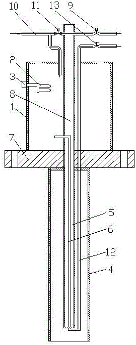
[0047] A fully automatic sampling method comprising the steps of:
[0048] a. Insert the filter of the automatic sampling device into the industrial pipeline to be sampled;
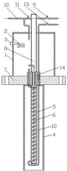
[0049] b. Close the blowback solenoid valve 11 through the PLC controller, pass instrument air or nitrogen into the thermal bath thermostat of the automatic sampling device, and turn on the electric heater 2; open the needle valve 13, and discharge the heated gas through the vent pipe 12 instrument air or nitrogen;
[0050] c. The sample gas in the industrial pipeline to be sampled enters the sampling pipe 8 after being filtered by a filter, and the sampling solenoid valve 9 is opened by the PLC controller to take out the sample gas;
[0051] d. After taking out the sample gas, open the backflush solenoid valve 11 through the PLC controller and close the sampling solenoid valve 9, and perform backflush cleaning on the filter with instrument air or nitrogen.
[0052] This embodiment is the most basic imp...
Embodiment 2
[0054] A fully automatic sampling method comprising the steps of:
[0055] a. Insert the filter of the automatic sampling device into the industrial pipeline to be sampled;
[0056] b. Close the blowback solenoid valve 11 through the PLC controller, pass instrument air or nitrogen into the thermal bath thermostat of the automatic sampling device, and turn on the electric heater 2; open the needle valve 13, and discharge the heated gas through the vent pipe 12 instrument air or nitrogen;
[0057] c. The sample gas in the industrial pipeline to be sampled enters the sampling pipe 8 after being filtered by a filter, and the sampling solenoid valve 9 is opened by the PLC controller to take out the sample gas;
[0058] d. After taking out the sample gas, open the backflush solenoid valve 11 through the PLC controller and close the sampling solenoid valve 9, and perform backflush cleaning on the filter with instrument air or nitrogen.
[0059] In the step b, the heating temperatur...
Embodiment 3
[0063] A fully automatic sampling method comprising the steps of:
[0064] a. Insert the filter of the automatic sampling device into the industrial pipeline to be sampled;
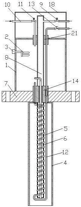
[0065] b. Close the backblowing solenoid valve 11 through the PLC controller, pass instrument air or nitrogen into the thermal bath thermostat of the automatic sampling device, and turn on the electric heater 2; open the needle valve 13, and discharge the heated gas through the vent pipe 12 instrument air or nitrogen;
[0066] c. The sample gas in the industrial pipeline to be sampled enters the sampling pipe 8 after being filtered by a filter, and the sampling solenoid valve 9 is opened by the PLC controller to take out the sample gas;
[0067] d. After taking out the sample gas, open the backflush solenoid valve 11 and close the sampling solenoid valve 9 through the PLC controller, and perform backflush cleaning on the filter with instrument air or nitrogen.
[0068] In the step b, the heating tempera...
PUM
 Abstract
Description
Claims
Application Information
 - R&D
- Intellectual Property
- Life Sciences
- Materials
- Tech Scout
- Unparalleled Data Quality
- Higher Quality Content
- 60% Fewer Hallucinations
Browse by: Latest US Patents, China's latest patents, Technical Efficacy Thesaurus, Application Domain, Technology Topic, Popular Technical Reports.
© 2025 PatSnap. All rights reserved.Legal|Privacy policy|Modern Slavery Act Transparency Statement|Sitemap|About US| Contact US: help@patsnap.com


