
Double-sided positioning splicing belt and the double-sided positioning connection method of the material belt

A connection method and a technology for splicing tapes, which are applied in the direction of thin material processing, film/sheet-like adhesives, and winding strips, etc., can solve the problem of easy loosening of two material tapes, irregular butt joint of material tapes, and uneven Easy to tear and other problems, to avoid the uneven butt joint of the material belt, improve the bonding effect, and improve the efficiency

Active Publication Date: 2018-02-09
SHENZHEN KHJ TECH
View PDF3 Cites 0 Cited by
  • Summary
  • Abstract
  • Description
  • Claims
  • Application Information

AI Technical Summary

Problems solved by technology

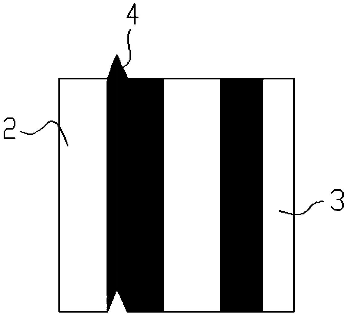
[0004] The traditional splicing belts are all positioned on one side, such as figure 1 , figure 2 As shown, it is covered with a layer of release paper 3 on the adhesive tape 1, and a positioning bar 2 is provided on one side of the release paper for correcting and aligning the two material strips to be connected. There is a positioning guide mark 4. When in use, the ends of the two material tapes to be bonded are butted against the positioning bar 2, and then the anti-sticking paper 3 is peeled off along the edge of the positioning edge, and the adhesive tape is turned over to make it It is bonded on the material tape, and finally the positioning edge and the transparent tape are removed together to complete the bonding process. For this kind of single-side positioning tape, although the material tape can be bonded more neatly to a certain extent, but in When using, after using the positioning bar to align the two material tapes, you need to remove the positioning bar and start bonding. In this way, when the material tape is pressed on the adhesive tape, the two material tapes are easy to loosen. It will lead to the problem that the butt joint of the tape is not neat, and the positioning bar 2 of the unilateral positioning tape is not easy to tear off, which is very inconvenient to use

Method used


Image

  • Double-sided positioning splicing belt and the double-sided positioning connection method of the material belt
  • Double-sided positioning splicing belt and the double-sided positioning connection method of the material belt
  • Double-sided positioning splicing belt and the double-sided positioning connection method of the material belt

Examples


Embodiment Construction

[0029] In order to make the purpose, technical solutions and advantages of the embodiments of the present invention clearer, the technical solutions in the embodiments of the present invention will be clearly described below in conjunction with the accompanying drawings in the embodiments of the present invention. Obviously, the described embodiments are the Some, but not all, embodiments are invented. Based on the embodiments of the present invention, all other embodiments obtained by persons of ordinary skill in the art without making creative efforts belong to the protection scope of the present invention.

[0030] Such as figure 1 , figure 2 As shown, the traditional unilateral positioning tape used for bonding material tapes includes an adhesive tape 1 covered with a layer of release paper 3 on the adhesive tape 1, and a positioning bar 2 is provided on the side of the adhesive tape 1, and the positioning bar 2 Stick it together with the release paper 3 covered by it, ...


PUM


Abstract

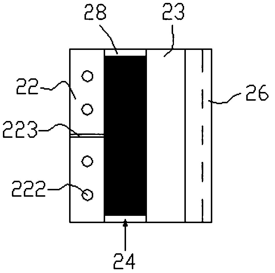
The invention relates to a splicing tape, in particular to a connecting tape and a connecting method for a material tape carrying electronic components, comprising a transparent tape (21), a release paper and a positioning bar arranged on the release paper , the positioning bar includes a first positioning bar (22) and a second positioning bar (23), forming a material-to-material area (24) that can just place the material belt (31) between the two, and in the material-to-material area (24 ) and between the second positioning bar (23) and the scotch tape (21) are provided with an adhesive tape (20); The first release paper (28) on the top, and the second release paper (26) between the second positioning bar (23) and the adhesive tape (20). Carry out double-sided positioning and connection of the material belt, correct the position of the material belt in the feeding area, and then peel off the corresponding release paper and positioning bar, and the material can be conveniently, quickly and accurately placed under the action of another positioning bar belt connected.

Description

technical field [0001] The invention relates to the field of splicing tapes, and more specifically relates to a splicing tape for connecting the splicing tapes and a method for connecting the splicing tapes. Background technique [0002] When assembling electronic products, traditional electronic components are generally large in size, and their assembly and use will be greatly restricted. Devices, thereby realizing high density, high reliability, miniaturization, low cost, and automation of production of electronic product assembly. Correspondingly, the automatic placement process for installing electronic components has been widely used. In the automatic placement process, the electronic components are preset in the component pits of the tape and fixed with a plastic film. The chip machine gradually opens the plastic film and pastes the electronic components to the appropriate position on the circuit board. [0003] When the material tape is sent into the automatic plac...

Claims


Application Information

Patent Timeline
Patent Type & Authority Patents(China)
IPC IPC(8): H05K3/30H05K13/02C09J7/20
CPCB65H21/00H05K13/00C09J7/20
Inventor 周宝范练群田健
Owner SHENZHEN KHJ TECH
Learn More