Simulation Method of Inductor and Nonlinear Equivalent Circuit Model of Inductor
A technology of equivalent circuit model and simulation method, which is applied in the direction of instruments, electrical digital data processing, complex mathematical operations, etc., can solve problems such as poor impedance characteristics, unsuitable circuit simulation, and excessive difference, and achieve the effect of simple structure
- Summary
- Abstract
- Description
- Claims
- Application Information
AI Technical Summary
Problems solved by technology
Method used
Image
Examples
Embodiment approach 2
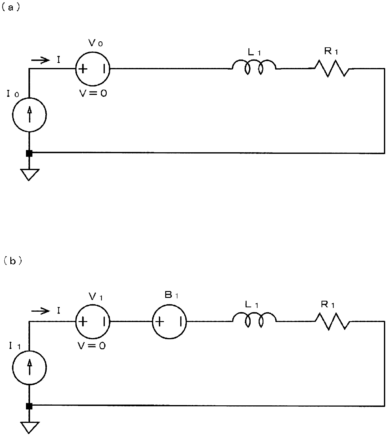
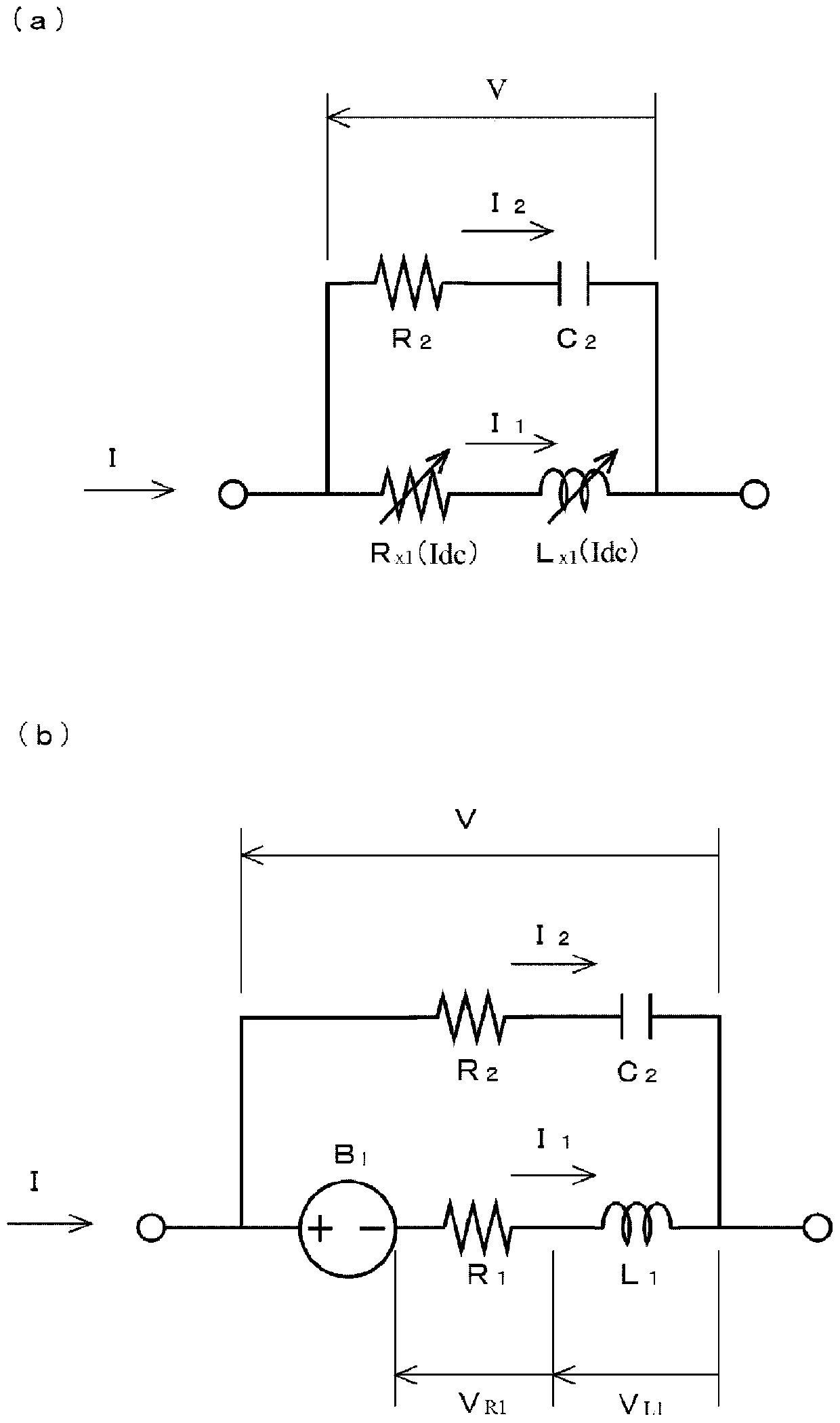
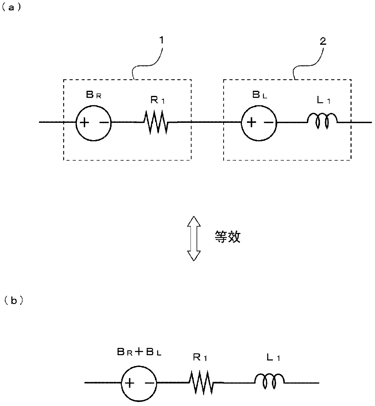
[0121] In the passive equivalent circuit model and the nonlinear equivalent circuit model of Embodiment 2, in the induction element L 1 with resistive element R 1 The inductive element L is connected in parallel on the series circuit of 2 with resistive element R 2 A series circuit of , thereby constituting a passive circuit element representing an equivalent circuit of an inductor as a simulation object. And, in the nonlinear equivalent circuit model shown in (b) of the same figure, the control voltage source B 1 connected in series to the sensing element L 1 and resistive element R 1 A series circuit, and with the control voltage source B 1 same control voltage source B 2 connected in series to the sensing element L 2 and resistive element R 2 series circuit. That is, in each equivalent circuit model of the second embodiment, the control voltage source B 1 and passive circuit components L 1 , R 1 A series circuit, and the control voltage source B 2 and passive c...
Embodiment approach 4
[0150] In Embodiment 4 Figure 17 In the passive equivalent circuit model shown in (a), in Figure 12 by the circuit element R X1 , R X2 , L X1 , L X2 The resistive element R and the inductive element L represented by are composed of a passive circuit element R that does not depend on the DC superimposed current Idc and can be regarded as a constant 1 , R 2 , L 1 , L 2 To represent. Figure 17 In the nonlinear equivalent circuit model shown in (b), the control voltage source B 1 connected in series to the sensing element above L 1 and resistive element R 1 A series circuit, with the control voltage source B 1 same control voltage source B 2 connected in series to the sensing element above L 2 and resistive element R 2 series circuit, which means Figure 12 The circuit element R X1 , R X2 , L X1 , L X2 . In each equivalent circuit model of Embodiment 4, with Figure 5 In the equivalent circuit models of the second embodiment shown, the control voltage sourc...
PUM
 Abstract
Description
Claims
Application Information
 - R&D
- Intellectual Property
- Life Sciences
- Materials
- Tech Scout
- Unparalleled Data Quality
- Higher Quality Content
- 60% Fewer Hallucinations
Browse by: Latest US Patents, China's latest patents, Technical Efficacy Thesaurus, Application Domain, Technology Topic, Popular Technical Reports.
© 2025 PatSnap. All rights reserved.Legal|Privacy policy|Modern Slavery Act Transparency Statement|Sitemap|About US| Contact US: help@patsnap.com


