Eureka AIR delivers breakthrough ideas for toughest innovation challenges, trusted by R&D personnel around the world.

Dust removal device

A technology of dust removal equipment and dust removal tubes, which is applied in the direction of dispersed particle separation, chemical instruments and methods, separation methods, etc., which can solve the problems of severe lung damage, dust remaining in the air, and limited dust adsorption effect, and improve separation efficiency. , Guarantee the separation quality and improve the effect of gas flow velocity

Active Publication Date: 2016-01-13
昭平县科学技术指导站
View PDF6 Cites 2 Cited by
  • Summary
  • Abstract
  • Description
  • Claims
  • Application Information

AI Technical Summary

Problems solved by technology

[0002] In the process of powder processing, a large amount of dust will be scattered in the air. These dusts will cause great damage to the lungs of the human body, and will cause harm to the operators and people around the production site.
In the prior art, the Chinese patent with the patent number of CN104785021A discloses a dust collector, which includes a shell, and the inside of the shell is provided with a vertical partition that divides the shell into an air inlet chamber and an air outlet chamber, and the air inlet chamber and the air outlet chamber The lower part is connected, the air inlet chamber and the air outlet chamber are respectively provided with an air inlet and an air outlet, and both the air inlet chamber and the air outlet chamber are provided with staggered diaphragms, the diaphragms are arranged obliquely, and the high end of the diaphragms is set on the shell On the side wall or vertical partition of the body, the lower end of the horizontal partition is suspended in the air. When this invention is used, the kinetic energy of the dust in the air is relatively large, and the adsorption of the dust by the vertical partition and the horizontal partition is limited, and some dust will remain. In the air, the invention did not propose a solution to this

Method used


Image

  • Dust removal device
  • Dust removal device

Examples


Embodiment Construction

[0017] The technical solution of the present invention will be further described below in conjunction with the accompanying drawings, but the scope of protection is not limited to the description.

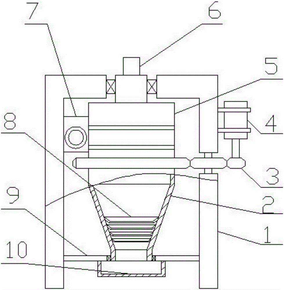
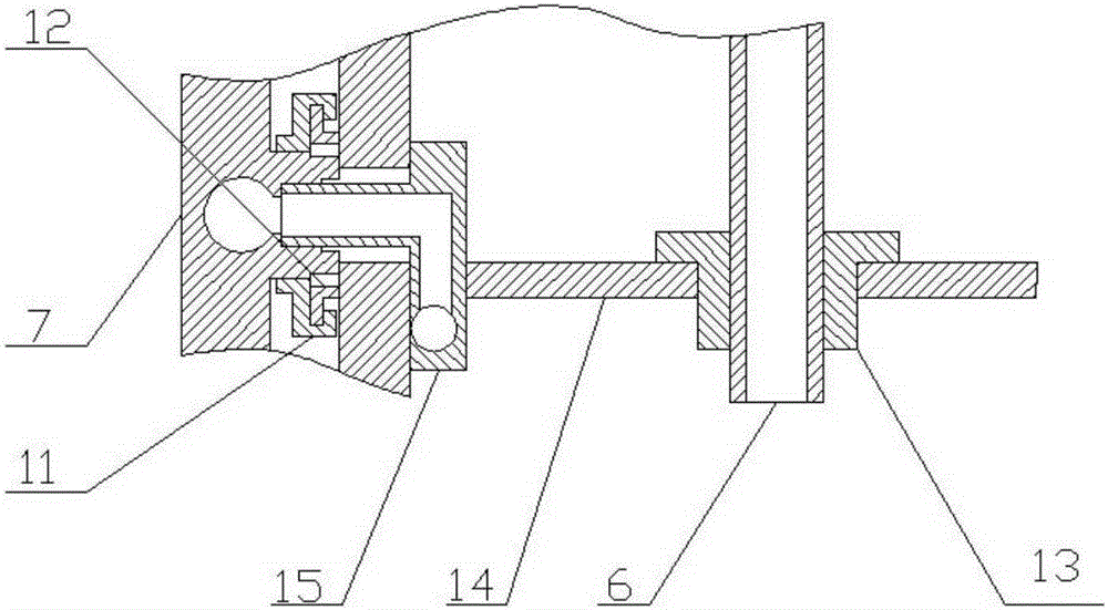
[0018] Such as figure 1 , figure 2 The shown dust removal equipment includes a frame 1, a dust removal pipe 2, a shield 5, an exhaust pipe 6, an air intake pipe 7, a nozzle 15, a liner 14 and a motor 4, and the upper section of the dust removal pipe 2 is a large cylinder shaped cavity, the middle section is a conical cavity, and the lower section is a small cylindrical cavity. The upper, middle and lower sections of the dust removal pipe 2 transition smoothly, and the shield 5 is installed on the frame 1. The cover 5 is connected to the upper edge of the dust removal pipe 2, the exhaust pipe 6 is installed at the center of the upper top surface of the shield 5, the air inlet pipe 7 is installed on the frame 1, and the air inlet pipe 7 is connected to the nozzle 15 connected, the...


PUM


Abstract

The invention discloses a dust removal device including a machine frame, a dust removal pipe, a protective cover, an exhaust pipe, an air inlet pipe, a nozzle, a lining plate and a motor; an upper section of the dust removal pipe is a large cylindrical cavity, the middle section of the dust removal pipe is a conical cavity, the lower section of the dust removal pipe is a small cylindrical cavity, and the upper section, the middle section and the lower section of the dust removal pipe are in smooth transition; the protective cover is mounted on the machine frame and is connected with an upper edge opening of the dust removal pipe; the exhaust pipe is mounted at the center of the upper top surface of the protective cover; the air inlet pipe is mounted on the machine frame and is communicated with the nozzle; the nozzle is mounted on the lining board; the lining plate is mounted on the exhaust pipe; the spray direction of the nozzle is tangent to the inner wall of the dust removal pipe; the dust removal pipe is vertically mounted on the machine frame and is connected to the motor. Through use of the motor, the dust removal pipe, the nozzle and the air inlet pipe, air containing dust performs rotational motion, the dust is separated through a centrifugal force, and the separation efficiency is improved.

Description

technical field [0001] The invention relates to the technical field of environmental protection equipment manufacturing, in particular to a dust removal equipment. Background technique [0002] During the process of powder processing, a large amount of dust will be scattered in the air, which will cause great damage to the lungs of the human body, and will cause harm to the operators and people around the production site. In the prior art, the Chinese patent with the patent number of CN104785021A discloses a dust collector, which includes a shell, and the inside of the shell is provided with a vertical partition that divides the shell into an air inlet chamber and an air outlet chamber, and the air inlet chamber and the air outlet chamber The lower part is connected, the air inlet chamber and the air outlet chamber are respectively provided with an air inlet and an air outlet, and both the air inlet chamber and the air outlet chamber are provided with staggered diaphragms, t...

Claims


Application Information

Patent Timeline
IPC IPC(8): B01D45/14
Inventor 严燕华
Owner 昭平县科学技术指导站
Why Eureka
Eureka Blog
Learn More