Horizontal machining center

A machining center, horizontal technology, applied in the direction of metal processing equipment, metal processing machinery parts, manufacturing tools, etc., can solve the problems of affecting the processing quality of parts, affecting the product qualification rate, poor repeat positioning accuracy, etc., and achieve high repeat positioning accuracy , the protection effect is obvious, and the effect that meets the requirements of processing accuracy

Active Publication Date: 2016-01-13
精诺(天津)数控科技有限公司
View PDF5 Cites 3 Cited by
  • Summary
  • Abstract
  • Description
  • Claims
  • Application Information

AI Technical Summary

Problems solved by technology

[0002] Horizontal machining centers are mainly used to process large parts, such as box parts or parts with deep holes. Such parts are widely used in aerospace, aviation, oil exploration, heavy industry machinery, etc., so the horizontal machining center There are also high requirements for precision. The horizontal centers in the market are mainly divided into fixed column type and fixed column type. These two structures mostly use the spindle box and column to move, and cooperate with the workbench to realize the machine tool. X, Y, Z axis three Displacement changes in three directions. Among them, the spindle ram feed type and the shaft table are fixed, but it is suitable for processing small and medium-sized multiple parts. For long and large heavy shaft parts such as oil probe rods, it is troublesome to clamp and position. Moreover, it must consume a large amount of power, and the repeat positioning accuracy is poor, which affects the processing accuracy, which in turn affects the processing quality of the parts, affects the product qualification rate, and increases the processing cost. To solve the above problems, it is necessary to provide a stable and high-precision Horizontal Machining Center

Method used


Image

  • Horizontal machining center
  • Horizontal machining center
  • Horizontal machining center

Examples


Embodiment Construction

[0030] The specific embodiments of the present invention will be described in detail below with reference to the accompanying drawings.

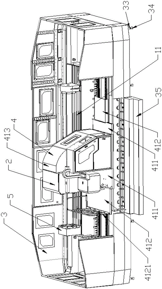
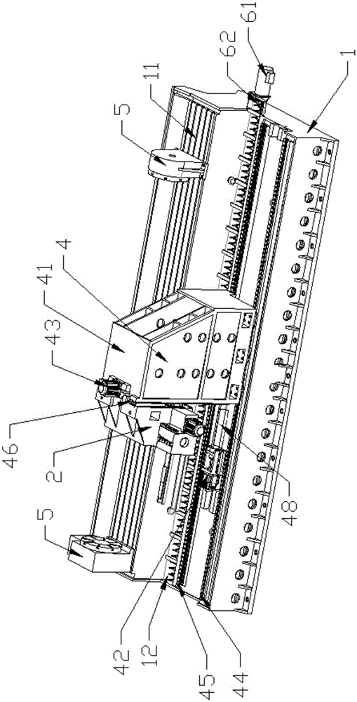
[0031] like figure 1 As shown, the present invention is a horizontal machining center, including a base 1 , a spindle head assembly 2 , a machine tool protective cover assembly 3 , a column assembly 4 and a turntable 5 .

[0032] like figure 1 , Figure 4 As shown, the column assembly 4 is arranged on the side above the base 1, the column assembly 4 and the base 1 are slidingly connected, and the end of the base 1 away from the installation column assembly 4 is the workbench 11, and the setting direction of the workbench 11 is the same as that of the column. The sliding direction of the assembly 4 is the same, the spindle head assembly 2 is set on one side of the column assembly 4, the spindle head assembly 2 is disposed facing the worktable 11 and is perpendicular to the X-direction end surface of the worktable 11, and the spindle head as...


PUM


Abstract

The invention provides a horizontal machining center. The horizontal machining center comprises a base, a main shaft head assembly and a stand column assembly. The stand column assembly is arranged on one side of the upper portion of the base. The stand column assembly is connected with the base in a sliding manner. The end, far away from the stand column assembly, of the upper portion of the base is provided with a workbench. The arrangement direction of the workbench is the same as the sliding direction of the stand column assembly. The main shaft head assembly is arranged on one side of the stand column assembly. The main shaft head assembly faces the workbench and is perpendicular to the X direction end face of the workbench. The main shaft head assembly is connected to the stand column assembly in a sliding manner. The main shaft head assembly comprises a main shaft box and a main shaft. The main shaft box is connected with the main shaft in the Z axis direction in a sliding manner. The main shaft can move in the X direction, the Y direction and the Z direction; and the workbench and the base are integrated, rigidity is good, a rotating table is arranged on the workbench, a large and heavy part can be completely machined though one time of clamping, and precision is high.

Description

technical field [0001] The invention belongs to the field of numerical control equipment, in particular to a horizontal machining center. Background technique [0002] Horizontal machining centers are mainly used to process large parts, such as box parts or parts with deep holes. Such parts are widely used in aerospace, aviation, oil exploration, heavy industry machinery, etc. There are also high requirements for accuracy. At present, the horizontal centers in the market are mainly divided into fixed-column type and fixed-column type. These two structures mostly use the spindle box and column movement, and cooperate with the movement of the worktable to realize the machine tool, X, Y, Z axis three axes. Displacement changes in each direction, among which the spindle ram feed type, the shaft table is fixed, but it is suitable for the processing of small and medium-sized parts, long and large heavy shaft parts such as oil probe rods, the clamping and positioning are troublesom...

Claims


Application Information

Patent Timeline
IPC IPC(8): B23Q1/01B23Q11/00B23Q1/25B23Q11/08
CPCB23Q1/015B23Q1/017B23Q1/25B23Q11/0042B23Q11/08B23Q2220/004B23Q2240/007
Inventor 王振飞
Owner 精诺(天津)数控科技有限公司
Why Eureka
Try Eureka