
An abrasive jet mixing device

A mixing device and abrasive jet technology, which is applied in the direction of abrasive feeding device, abrasive material, explosion generating device, etc., can solve the problems of uneven abrasive supply, easily damaged nozzles, and insufficient turbulent mixing of water jets, etc., to achieve continuous and uniform Supply, continuous and uniform supply of abrasives, and the effect of improving energy transfer efficiency

Inactive Publication Date: 2018-08-10
SUZHOU INSTITUE OF WUHAN UNIV
View PDF5 Cites 0 Cited by
  • Summary
  • Abstract
  • Description
  • Claims
  • Application Information

AI Technical Summary

Problems solved by technology

At present, the post-mixing abrasive water jet system has been widely used, but it still has the problem that the abrasive and the high-speed water jet cannot be fully turbulently mixed. For example, some abrasive particles have been ejected before they are fully accelerated. However, it is difficult for the abrasive particles to enter the center of the water jet and be accelerated, which significantly reduces the energy transfer efficiency of the aqueous medium to the abrasive particles and the energy of the abrasive jet.
The pre-mixed abrasive jet is still in the research and development stage and is gradually being applied. It can improve the energy transfer efficiency of the aqueous medium to the abrasive, but it may have the problems of uneven abrasive supply and easy damage to the nozzle.

Method used


Image

  • An abrasive jet mixing device
  • An abrasive jet mixing device
  • An abrasive jet mixing device

Examples


Embodiment Construction

[0012] The technical solution of the present invention will be further specifically described below in conjunction with the accompanying drawings.

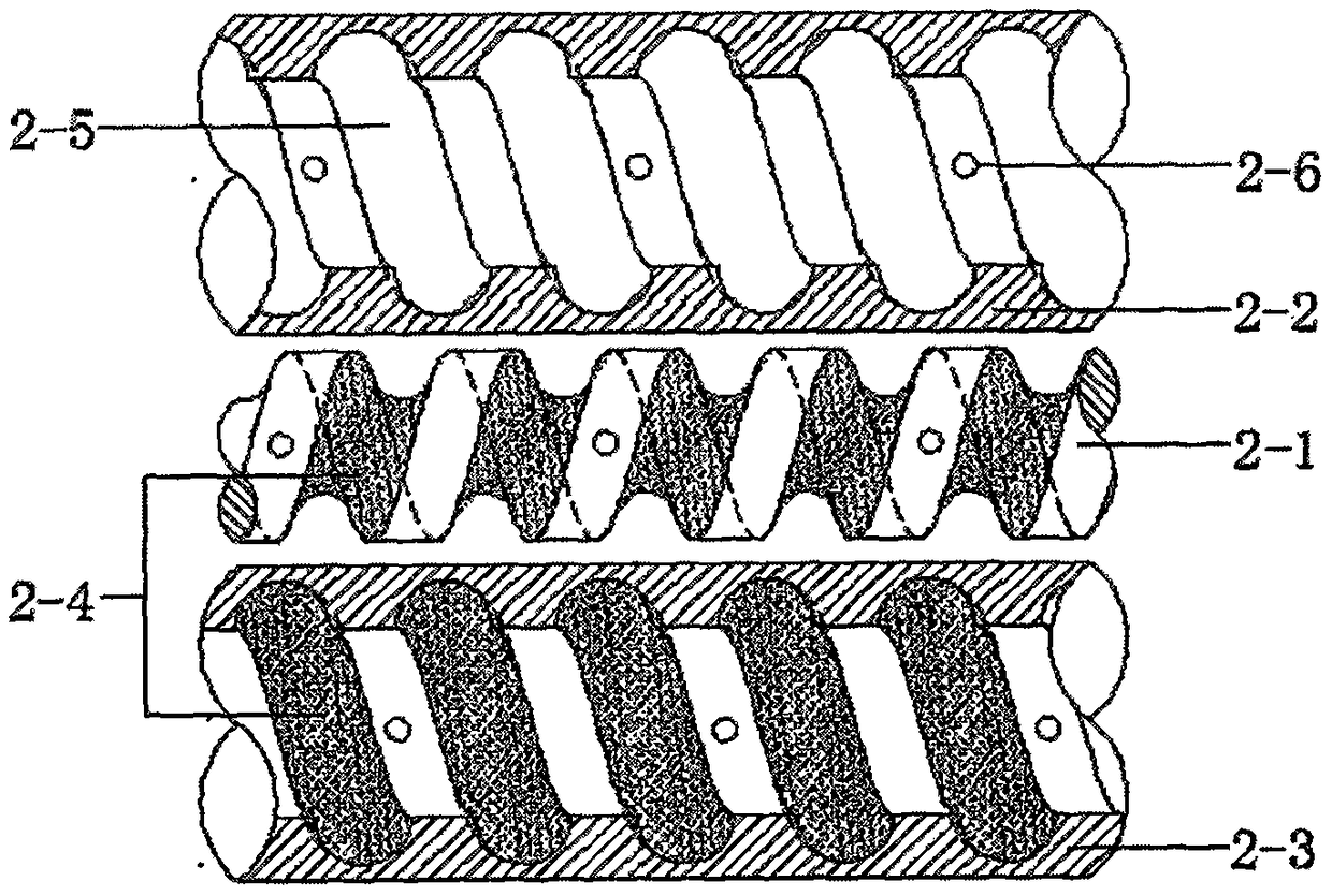
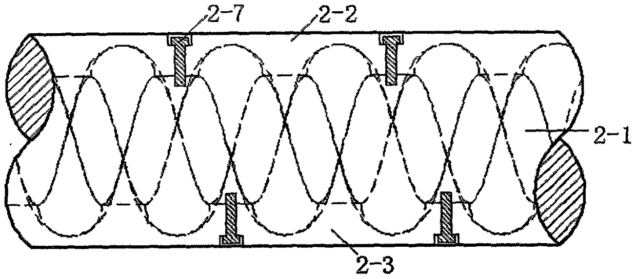
[0013] See attached Figure 1-3 , an abrasive jet mixing device comprising an abrasive supply system and an abrasive mixing system. The abrasive supply system mainly includes a mixing chamber (3), an abrasive barrel (4), a water jet branch (5), a flow valve (6), etc.; the abrasive mixing system mainly includes a spiral mixing tube (2), a high pressure Water pipe (7) etc. The tube core (2-1), the upper mixing chamber (2-2) and the lower mixing chamber (2-3) are all provided with spiral grooves (2-5) and screw holes (2-6); The spiral groove (2-5) is provided with a wear-resistant material (2-4), such as hard alloy wear-resistant material, ceramic wear-resistant material and the like. The spiral mixing tube (2) is composed of a tube core (2-1), an upper mixing chamber (2-2), a lower mixing chamber (2-3), and connected by screws (2...


PUM


Abstract

The invention discloses an abrasive material jet mixing method and device. The abrasive material jet mixing device mainly comprises an abrasive material supply system and an abrasive material mixing system. The abrasive material supply system comprises a mixing cavity, an abrasive material cylinder, a water jet branch circuit, a flow valve and the like. The abrasive material mixing system comprises a spiral mixing pipe, a high-pressure water pipe and the like. Abrasive material particles in the abrasive material cylinder fall into a mixing cavity under the effect of gravity. A high-pressure water jet is divided by the water jet branch circuit. Part of the high-pressure water jet enters the mixing cavity to be mixed with abrasive materials. The flow valve arranged on the water jet branch pipe can control the water flow amount of the branch circuit. The abrasive material particles enter the high-pressure water pipe after being preliminarily mixed in the mixing cavity and are then conveyed into the spiral mixing pipe through the water jet. The abrasive materials are ejected out through a spray nozzle to work after being sufficiently mixed with the water jet and accelerated in the spiral mixing pipe. Compared with an existing abrasive material jet mixing method and device, the abrasive material jet mixing method and device have the beneficial effects that the energy transmission efficiency of the water jet for the abrasive materials is high, the abrasive materials are uniformly supplied, the structure is simple and wear resistance is achieved.

Description

technical field [0001] The invention relates to the field of abrasive jet technology, in particular to an abrasive jet mixing device. Background technique [0002] Since the abrasive jet technology was applied to oil well drilling in the 1960s and greatly improved the drilling efficiency, it has gradually received widespread attention. Because the abrasive jet system is simple, low in cost, and its cutting efficiency is 8 to 10 times higher than that of water jet under the same conditions, it has been widely used in cleaning, rust removal, cutting and breaking rocks. Abrasive jets are divided into post-mix and pre-mix according to their mixing methods. At present, the post-mixing abrasive water jet system has been widely used, but it still has the problem that the abrasive and the high-speed water jet cannot be fully turbulently mixed. For example, some abrasive particles have been ejected before they are fully accelerated. However, it is difficult for abrasive particles t...

Claims


Application Information

Patent Timeline
Patent Type & Authority Patents(China)
IPC IPC(8): B24C5/00B24C5/02B24C7/00
Inventor 刘全杨晓峰
Owner SUZHOU INSTITUE OF WUHAN UNIV
Learn More