
Vehicle self-ignite alarming apparatus

Inactive Publication Date: 2016-01-13
邹民勇
View PDF9 Cites 0 Cited by
  • Summary
  • Abstract
  • Description
  • Claims
  • Application Information

AI Technical Summary

Problems solved by technology

[0002] At present, the short circuit of the car due to engine failure and other reasons can easily cause the engine compartment to burn and cause a fire.
At present, the engine compartment generally uses instruments to display the water temperature, but the temperature in the engine compartment is not displayed in real time. Once the temperature in the engine compartment is found to be too high, it is irremediable.
[0003] Chinese patent, application number is 201220725288.5, the name is a kind of automobile fire alarm system based on single-chip microcomputer, which uses single-chip microcomputer to cooperate with various sensors, which is not predictable and can only alarm after a fire occurs
Automobile fire alarm, the application number is 200920176999.X, using a thermistor, but using this device and using a temperature detection controller, the circuit structure will be more complicated and the cost will be higher
Moreover, the thermistor needs to be connected in series in the automobile wires, which changes the original automobile wiring, causes the wires to be exposed, etc., and increases potential safety hazards.
The application number is 201220223406.2, and the name is the automobile fire alarm system. The alarm can only be issued after the fire occurs, and it is not predictable.

Method used


Image

  • Vehicle self-ignite alarming apparatus

Examples


Embodiment Construction

[0014] The present invention will be described in further detail below in conjunction with specific embodiments.

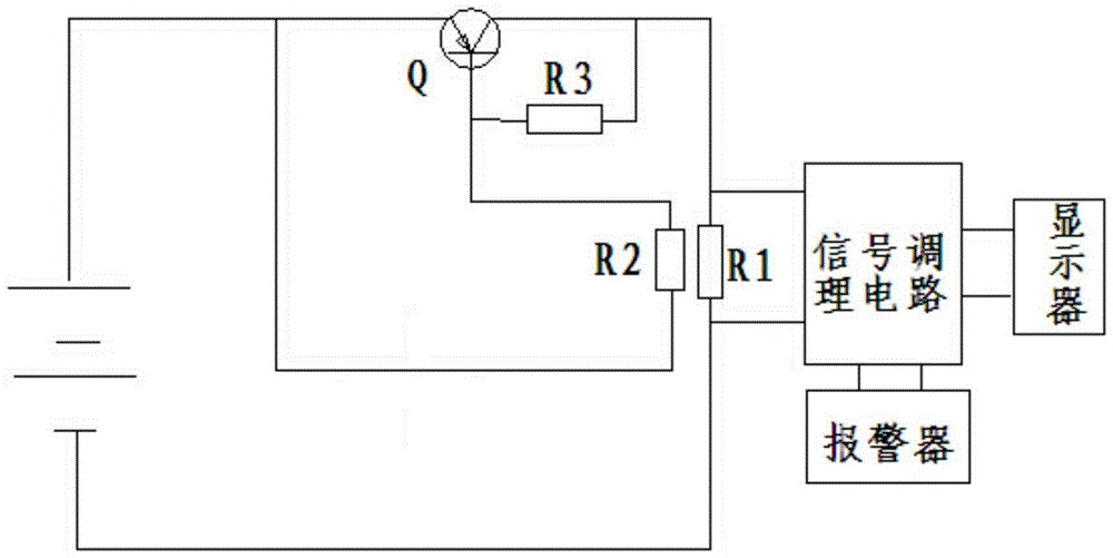
[0015] Such as figure 1 As shown, a car spontaneous combustion alarm device includes a PNP-type triode Q, the emitter of the triode Q is connected to the positive pole of the power supply, and the collector of the triode Q is connected to the positive pole of the power supply after being connected in series with the thermistor R2. The thermistor R2 has a negative temperature coefficient of resistance; the base of the transistor Q is connected to the negative pole of the power supply after the base of the transistor Q is connected in series with the first resistor, and a second resistor R3 is also connected in series between the base and the collector of the transistor Q;

[0016] Both ends of the first resistor R1 are respectively connected to two input terminals of a signal conditioning circuit, an output terminal of the signal conditioning circuit is connected t...


PUM

PropertyMeasurementUnit
Thicknessaaaaaaaaaa

Abstract

A vehicle self-ignite alarming apparatus comprises a triode, wherein an emitting electrode of the triode is connected to a positive electrode of a power source; a collector electrode of the triode is connected to the power source positive electrode after the collector electrode is in serials connection with a thermal-sensitive electric resistor; a base electrode of the triode is connected to a negative electrode of the power source after the base electrode of the triode is in serials connection with a first electric resistor; a second electric resistor is also parallelly connected between the base electrode and the collector electrode of the triode; two ends of the first electric resistor are respectively connected to two input ends of a signal regulating circuit; an output end of the signal regulating circuit is connected to a displayer; and an alarming output end of the signal regulating circuit is connected to an alarming device. When the temperature of the thermal-sensitive resistor is changed, the electric current flowing through the two ends of the first electric resistor will also changed and the voltage at the two ends of the first electric resistor; the signal regulating circuit receives voltage signals at the two ends of the first electric resistor and the signals are outputted after the signals are processed, which signifies that the electric signals of the temperature in an engine compartment is displayed by a displayer; and when the temperature in the engine compartment exceeds the preset signals, the output alarming signals are controlled by the signal regulating circuit to give out alarm.

Description

technical field [0001] The invention relates to the technical field of generators, in particular to an automobile spontaneous combustion alarm device. Background technique [0002] At present, due to engine failure and other reasons, the circuit of the car is short-circuited, which can easily cause the engine compartment to burn and cause a fire. At present, the engine compartment generally uses instruments to display the water temperature, but the temperature in the engine compartment is not displayed in real time. When the temperature in the engine compartment is found to be too high, it is irremediable. [0003] Chinese patent, application number is 201220725288.5, the name is a kind of car fire alarm system based on single-chip microcomputer, adopts single-chip microcomputer to cooperate with various sensors, is not predictable, can only report to the police after a fire breaks out. The automobile fire alarm, whose application number is 200920176999.X, uses a thermistor...

Claims


Application Information

Patent Timeline
IPC IPC(8): B60R16/023
CPCB60R16/0232
Inventor 邹民勇
Owner 邹民勇
Learn More