Supercharge Your Innovation With Domain-Expert AI Agents!

Borehole Layout Method for Gas Drainage During Initial Mining and Recovery of Fully Mechanized Mining Face with Large Mining Height

A fully-mechanized mining face and gas drainage technology, which is applied in the direction of gas discharge, safety devices, mining equipment, etc., can solve the problem of high-level drilling not functioning, pressure relief gas rushing, and large gas gushing out of goafs, etc. problems, to achieve the effect of increasing the drainage volume and utilization rate, reducing the amount of gas gushing out, and reducing the gas pressure

Active Publication Date: 2017-05-10
SHANXI JINMEI GRP TECH RESEACH INST +1
View PDF5 Cites 0 Cited by
  • Summary
  • Abstract
  • Description
  • Claims
  • Application Information

AI Technical Summary

Problems solved by technology

[0002] Gas drainage technology in goafs with high-level drilling is widely used as an effective method to control gas in goafs. However, in the initial stage of mining in fully mechanized mining working faces with large mining heights, the old roof of the coal seam has not been crossed, and the cracks in the roof are not fully developed. High-level drilling cannot Play a role
However, in the early stage of mining, due to the production process and other factors, the amount of coal left in the goaf is large, and the gas emission in the goaf is relatively large. area phenomenon

Method used


Image

  • Borehole Layout Method for Gas Drainage During Initial Mining and Recovery of Fully Mechanized Mining Face with Large Mining Height
  • Borehole Layout Method for Gas Drainage During Initial Mining and Recovery of Fully Mechanized Mining Face with Large Mining Height
  • Borehole Layout Method for Gas Drainage During Initial Mining and Recovery of Fully Mechanized Mining Face with Large Mining Height

Examples


Embodiment Construction

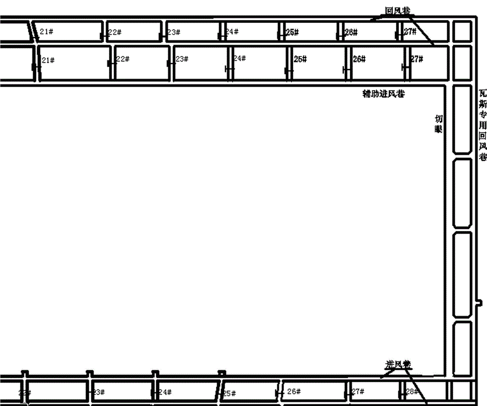
[0031] The roadway layout of fully mechanized mining face with large mining height is as follows: figure 1 As shown, it is generally arranged as a "three-inlet and two-return" ventilation system. The entire coal mining area is composed of five roadways, gas return airways, and cutouts.

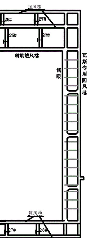
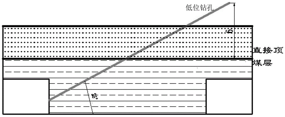
[0032] The specific implementation method of low-level drilling: the low-level drilling is relatively short, and ordinary drilling rigs are used to drill holes from the special gas return airway to the roof of the cut hole. 6±1m, 30±2m in length, and 10~20m between adjacent low-level drill holes. Such as figure 2 with image 3 shown.

[0033] The specific implementation method of the middle hole: use a kilometer directional drilling rig to construct the middle hole at the appropriate position in the roadway on the return air side. The hole layers are arranged within the range of 6~25m from the coal seam roof (directly above the roof, below the old roof), and in the lateral direction withi...


PUM


Abstract

The invention relates to a gas drainage drilling arrangement method during initial mining and back mining of a fully mechanized mining face with a large mining height, which mainly solves the problem of gas exceeding the limit during the initial mining and recovery of a fully mechanized mining face with a large mining height. The technical solution of the present invention is: arrange low-level boreholes in the gas-specific return airway of the fully mechanized mining face to mainly extract coal and gas left over from the initial mining section; aim at the problem that high-level boreholes cannot play a role during the initial mining period, arrange mid-level boreholes Drain the gas in the goaf; in view of the problem that the gas in the lower adjacent coal seam flows to the working face during the initial mining and recovery of the working face, arrange the gas interception boreholes in the lower adjacent layer, and arrange the high-level drilling to drain the goaf during the normal recovery of the working face For gas, the gas in the goaf is drained in an orderly manner through low-level holes, middle-level holes, and high-level holes, and the gas in the lower adjacent layers is drained through interception holes on the bottom plate, so as to improve the gas extraction volume and utilization rate, thereby reducing the gas in the goaf The gushing amount is reduced, the gas pressure of the wind exhaust is reduced, the advancing speed of the working face is accelerated, and the coal production is increased.

Description

technical field [0001] The invention relates to an underground gas drainage drilling technology, in particular to a gas drainage drilling arrangement method during initial mining and normal recovery of a fully mechanized mining face with a large mining height. Background technique [0002] Gas drainage technology in goafs with high-level drilling is widely used as an effective method to control gas in goafs. However, in the initial stage of mining in fully mechanized mining working faces with large mining heights, the old roof of the coal seam has not been crossed, and the cracks in the roof are not fully developed. High-level drilling cannot Play a role. However, in the initial stage of mining, due to the production process and other factors, the amount of coal left in the goaf is large, and the gas emission in the goaf is relatively large. area phenomenon. For the gas control during the initial mining of the fully mechanized mining face with large mining height, it is ma...

Claims


Application Information

Patent Timeline
Patent Type & Authority Patents(China)
IPC IPC(8): E21F7/00
CPCE21F7/00
Inventor 张国亮刘立州赵学良申晋伟尚玮炜吴晋军罗华贵陈备王宁
Owner SHANXI JINMEI GRP TECH RESEACH INST
Features
  • R&D
  • Intellectual Property
  • Life Sciences
  • Materials
  • Tech Scout
  • Unparalleled Data Quality
  • Higher Quality Content
  • 60% Fewer Hallucinations
Learn More