Eureka AIR delivers breakthrough ideas for toughest innovation challenges, trusted by R&D personnel around the world.

Cyclic spiral cavity sodium-filled air valve with spiral blade

A spiral blade, circulating technology, applied in the field of circulating spiral cavity sodium flush valve, can solve the problems of affecting the uniformity of exhaust valve heat dissipation, reducing the overall quality of the valve, reducing the life of the exhaust valve, etc., to make up for the mechanical strength, The effect of improving circulation and reducing carbon deposition

Inactive Publication Date: 2016-01-13
CHONGQING QIFU MACHINERY
View PDF13 Cites 1 Cited by
  • Summary
  • Abstract
  • Description
  • Claims
  • Application Information

AI Technical Summary

Problems solved by technology

In order to solve this problem, people drill a hole in the valve stem of the exhaust valve to form a cavity. The melting point of metal sodium is 97.81°C. Under the premise of a reasonable hollow cavity volume, when the valve is working, the temperature rises rapidly. Metal sodium changes from solid to liquid at high temperature, and moves up and down in the hollow cavity to continuously scour the valve face and valve stem, effectively transfer the heat load at the end of the valve face to the valve stem, and then cool the exhaust valve through the water passage in the cylinder head , which improves the heat dissipation of the exhaust valve and effectively reduces the heat load on the valve surface. In addition, the specific gravity of metal sodium is small, the overall mass of the valve becomes smaller, and the stiffness of the valve becomes stronger. Under the same conditions, the deformation of the valve is less Small; however, there is a problem with the existing hollow sodium-filled exhaust valve: the heat at the center of the valve neck and the end face of the valve head is not easy to be smoothly conducted away, and it is the place where the temperature gathers, which will affect the heat dissipation uniformity of the exhaust valve , reducing exhaust valve life

Method used


Image

  • Cyclic spiral cavity sodium-filled air valve with spiral blade
  • Cyclic spiral cavity sodium-filled air valve with spiral blade
  • Cyclic spiral cavity sodium-filled air valve with spiral blade

Examples


Embodiment Construction

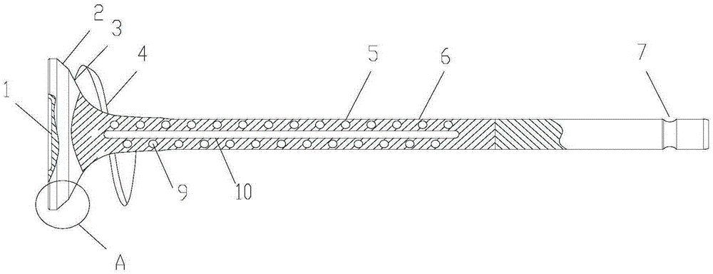
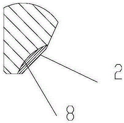
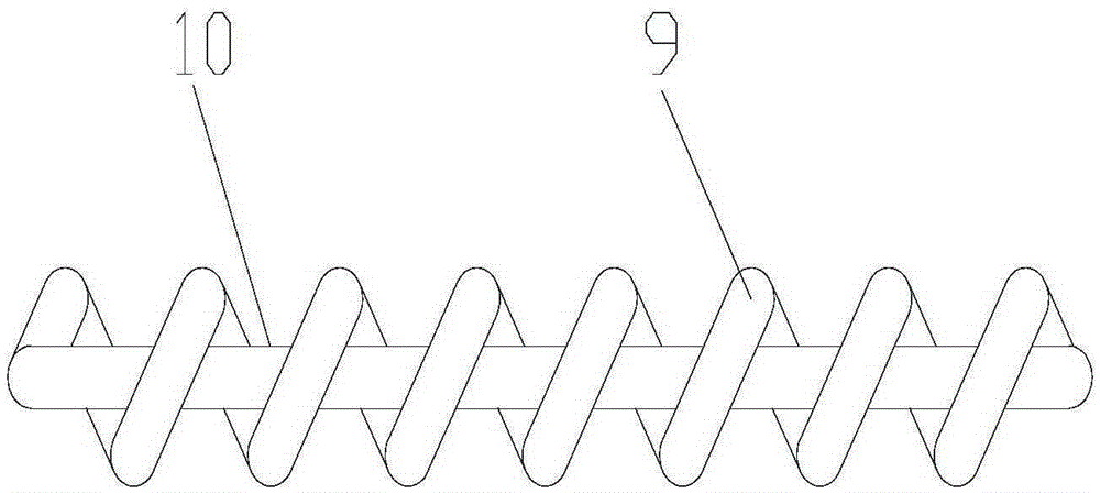
[0016] figure 1 It is a structural schematic diagram of the present invention, figure 2 for figure 1 In the partial enlarged view of A, as shown in the figure, the circulating spiral cavity flushing sodium valve with spiral blades in this embodiment includes a valve head 3 and a valve stem, and the outer wall of the valve head 3 is provided with a To the extended spiral blade 4, a circulating spiral flow channel 9 is provided inside the valve stem, and the circulating spiral flow channel 9 includes a spiral flow channel extending axially along the valve stem and a return flow channel 10 connecting the first and last ends of the spiral flow channel, The circulating spiral flow channel 9 is flushed with sodium, the surface of the valve stem is provided with a chrome-plated layer 6, and the valve head 3 is provided with an annular groove 8 along its circumference, and the inner groove 8 is covered with a surfacing layer 2 and the surface of the surfacing layer 2 is a conical su...


PUM


Abstract

The invention discloses a cyclic spiral cavity sodium-filled air valve with a spiral blade. The spiral blade extending in the axial direction of an air valve head is arranged on the outer side wall of the air valve head. A cyclic spiral flow channel is arranged in an air valve rod and comprises a spiral flow channel extending in the axial direction of the air valve rod and a backflow channel making the front end and the tail end of the spiral flow channel communicated. The spiral flow channel is filled with sodium. A chromium-plated layer is arranged on the surface of the air valve rod. An annular groove is formed in the air valve head circumferentially and covered with a bead welding layer. The surface of the bead welding layer is a conic face. By the adoption of the cyclic spiral cavity sodium-filled air valve with the spiral blade, heat accumulated on the throat of the air valve and the center of the end face of the air valve head can be better conducted away, so that the air valve dissipates heat evenly.

Description

technical field [0001] The invention relates to the field of engine parts, in particular to a circulation type spiral cavity flushing sodium valve with spiral blades. Background technique [0002] In the past, the gasoline engine exhaust valve was made of solid exhaust valve, the head of the exhaust valve was made of high temperature resistant austenite material, the rod was made of martensite material, and then processed by welding, surface treatment and other processes. Exhaust valves of this structure and process can only be used on naturally aspirated gasoline engines whose exhaust temperature does not exceed 750°C. In a supercharged engine, due to the use of compressed air intake technology (specifically turbocharging, supercharging and dual supercharging), the combustion explosion pressure in the cylinder is higher than that of natural suction, and the temperature in the cylinder is also higher than that of natural gas. When the intake is high, the temperature of the ...

Claims


Application Information

Patent Timeline
Patent Type & Authority Applications(China)
IPC IPC(8): F01L3/14F01L3/06F01L3/04F01L3/20
CPCY02T10/12
Inventor 王明杨梁绍辉
Owner CHONGQING QIFU MACHINERY
Why Eureka
Eureka Blog
Learn More