DC source full-coverage automatic test system

A technology of automated testing and DC power supply, applied in the direction of power supply testing, etc., can solve problems that affect test accuracy and test efficiency, cumbersome test process, and fatigue of engineers, so as to improve test efficiency, reduce workload, and avoid cumbersome effects

Inactive Publication Date: 2016-01-13
LANGCHAO ELECTRONIC INFORMATION IND CO LTD
View PDF10 Cites 22 Cited by
  • Summary
  • Abstract
  • Description
  • Claims
  • Application Information

AI Technical Summary

Problems solved by technology

This action is required for each test, the test process is cumbersome and inefficient, and i

Method used


Image

  • DC source full-coverage automatic test system
  • DC source full-coverage automatic test system
  • DC source full-coverage automatic test system

Examples


Example Embodiment

[0019] Example 1:

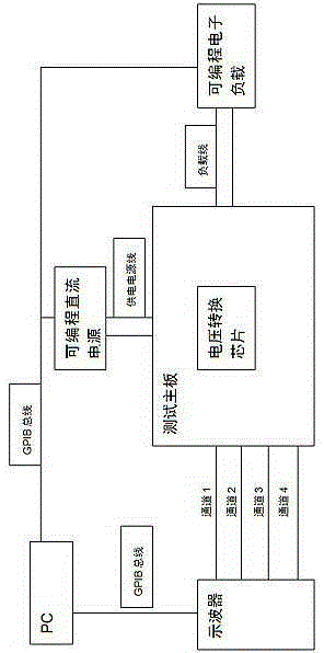
[0020] Such as figure 1 As shown, a DC power supply full coverage automated test system, the test system includes a test motherboard, a programmable DC power supply, a programmable electronic load, an oscilloscope, and a PC (ie: PersonalComputer), wherein the programmable DC power supply output terminal is connected to the test The main board provides power to the main board; the output terminal of the voltage conversion chip of the programmable DC power supply is connected to the programmable electronic load; the four channels of the oscilloscope are connected to the signal to be captured in turn, and channel 1 is connected to the input voltage terminal before the programmable DC power supply voltage conversion. Channel 2 is connected to the enable signal of the voltage conversion chip of the programmable DC power supply, channel 3 is connected to the voltage output terminal of the programmable DC power supply, and channel 4 is connected to the PowerGood signa...

Example Embodiment

[0021] Example 2:

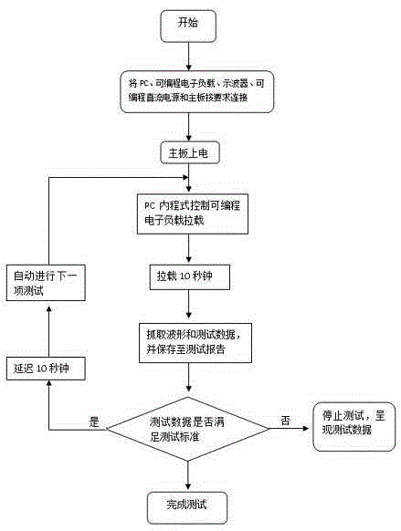
[0022] Such as figure 2 As shown, on the basis of Embodiment 1, the operation steps of the method described in this embodiment are as follows:

[0023] 1) Prepare to test the main board, set the DC power voltage conversion chip on the test main board, connect the programmable DC power supply output terminal to the test main board, supply power to the main board, and connect the programmable DC power supply output terminal to be tested to the programmable DC electronic load. Connect the four channels of the oscilloscope to the signal to be captured in sequence, channel 1 to the input voltage terminal before the programmable DC power supply voltage conversion, channel 2 to the enable signal of the programmable DC power voltage conversion chip, and channel 3 to the programmable DC power supply The voltage output terminal, channel 4 connects to the PowerGood signal of the programmable DC power supply;

[0024] 2) Connect the programmable DC electronic load, the osci...

Example Embodiment

[0026] Example 3:

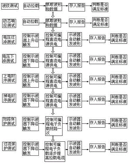
[0027] Such as image 3 As shown, on the basis of embodiment 1, the test data stored in the test report in this embodiment will be compared with the existing test standards in the report. If the test standards are met, the system will automatically perform the next test; if If the test standards are not met, the system will automatically uninstall, and automatically open the test report to display the test results.


PUM


Abstract

The invention discloses a DC source full-coverage automatic test system. The test system comprises a test mainboard, a programmable DC source, a programmable electronic load, an oscilloscope and a PC. The output end of the programmable DC source is connected with the test mainboard for supplying power to the mainboard; the output end of a voltage conversion chip of the programmable DC source is connected with the programmable electronic load; a first channel of the oscilloscope is connected with the an input voltage end before voltage conversion of the programmable DC source, a second channel is connected with enabling signals of the voltage conversion chip of the programmable DC source, a third channel is connected with the voltage output end of the programmable DC source, and a fourth channel is connected with Power Good signals of the programmable DC source; and the programmable electronic load, the oscilloscope and the programmable DC source are respectively connected with the PC through a GPIB bus, and the PC is internally provided with a written program for controlling the programmable electronic load, the oscilloscope and the programmable DC source.

Description

technical field [0001] The invention relates to the field of direct current power supply testing and the technical field of voltage conversion, in particular to an automatic test system for full coverage of direct current power supply. Background technique [0002] With the development of VLSI technology, the working voltage of the chip is getting lower and lower, while the working speed is getting faster and faster, the power consumption is getting bigger and bigger, and the density of the single board is getting higher and higher. Therefore, higher requirements are placed on the stability of the power supply system within the entire working frequency band. The test of the power supply system has become more and more concerned by power engineers at the present stage. The data of the power supply test directly reflects whether the group of power supplies meets the working requirements at the initial design stage, and various test items for the power supply system become imp...

Claims


Application Information

Patent Timeline
IPC IPC(8): G01R31/40
Inventor 孙辉柏春
Owner LANGCHAO ELECTRONIC INFORMATION IND CO LTD
Why Eureka
Try Eureka