Dielectric waveguide filter

一种介质波导、滤波器的技术,应用在介质波导滤波器领域,能够解决装配复杂、交叉耦合强度弱、效率低等问题,达到易于装配、结构工艺简洁、提高灵活性的效果

Active Publication Date: 2016-01-13
SHENZHEN SAMSUNG COMM TECH RES +1
View PDF4 Cites 40 Cited by
  • Summary
  • Abstract
  • Description
  • Claims
  • Application Information

AI Technical Summary

Problems solved by technology

The existing technical problems are: on the one hand, the parts of the product are increased, which is cumbersome in assembly and fixing, and the efficiency is low
On the other hand, the cross-coupling provided by this structure is weak and difficult to strengthen, which further increases the difficulty of design
[0006] The third solution is the metal probe structure applied to the coaxial cavity filter to generate negative cross-coupling. The main disadvantage of this solution is that the metal probe needs to be supported by a medium, and the assembly is more complicated.

Method used


Image

  • Dielectric waveguide filter
  • Dielectric waveguide filter
  • Dielectric waveguide filter

Examples


Embodiment Construction

[0033] The following will clearly and completely describe the technical solutions in the embodiments of the present invention with reference to the accompanying drawings in the embodiments of the present invention. Obviously, the described embodiments are only some, not all, embodiments of the present invention. Based on the embodiments of the present invention, all other embodiments obtained by persons of ordinary skill in the art without creative efforts fall within the protection scope of the present invention.

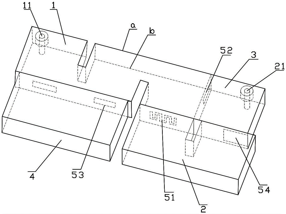
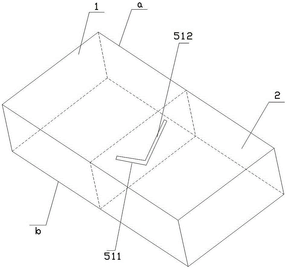
[0034] see Figure 1-Figure 2 , is a schematic structural diagram of an embodiment of a dielectric waveguide filter provided by the present invention, the dielectric waveguide filter in this embodiment includes:

[0035] The first resonator 1 has a dielectric block covered with a conductive layer on the surface of the dielectric block, the second resonator 2 has a dielectric block covered with a conductive layer on the surface of the dielectric block, and the third...


PUM


Abstract

The embodiment of the invention provides a dielectric waveguide filter, and the filter at least comprises a first resonator which is provided with a dielectric block, wherein the surface of the dielectric block is covered with a conductive layer; and a second resonator which is provided with a dielectric block, wherein the surface of the dielectric block is covered with a conductive layer. The contact surfaces of the first and second resonators are provided with coupling windows, thereby exposing the mediums of the first and second resonators. The mediums are used for the coupling between the first and second resonators. The sizes of the length of the coupling windows are set to be greater than the half-wavelength of the working frequency of the filter, so as to enable the coupling polarities between the first and second resonators to be opposite. According to the embodiment of the invention, the filter can enable the coupling polarities between the first and second resonators to be opposite, and generates negative coupling. The filter is flexible in topological structure, is simple in structure, and is easy to assemble.

Description

technical field [0001] The invention relates to a radio frequency filter, in particular to a dielectric waveguide filter. Background technique [0002] With the development of the filter industry, miniaturization and light weight have gradually become a trend. The dielectric waveguide can greatly reduce the size of the product, and has the advantages of high Q value and small temperature drift. It is a good miniaturization solution. [0003] The current dielectric waveguide filter and cavity filter still have the technical problems of complex cross-coupling (negative coupling) structure, inflexibility, and difficult implementation. For example: the existing dielectric waveguide filters that generate cross-coupling mainly have the following three forms: [0004] The first is the solution of the metal probe structure, which can generate negative cross-coupling. During implementation, the medium needs to be punched, and then the metal probe is inserted into the medium. Alth...

Claims


Application Information

Patent Timeline
Patent Type & Authority Applications(China)
IPC IPC(8): H01P1/20
CPCH01P1/208H01P1/20H01P1/2002H01P1/207H01P7/10H01P1/2082H01P1/2084
Inventor 康海聚蔡磊
Owner SHENZHEN SAMSUNG COMM TECH RES
Why Eureka
Try Eureka