Remote backup power supply automatic switching method and system

A technology of automatic switching and backup power, applied in the field of electric power, can solve problems such as long power outages, line power outages, inapplicability, etc., and achieve high maintainability and strong compatibility

Inactive Publication Date: 2016-01-13
DALI POWER SUPPLY BUREAU YUNNAN POWER GRID +1
View PDF4 Cites 9 Cited by
  • Summary
  • Abstract
  • Description
  • Claims
  • Application Information

AI Technical Summary

Problems solved by technology

[0002] With the development of urban and rural construction, users have higher and higher requirements for power supply reliability, which puts forward higher requirements for the quality of the original power supply and distribution equipment and the reliability of the power supply and distribution network. Most of the power supply network adopts radial power supply. This power supply method has many disadvantages. Once a fault occurs somewhere, it will cause a large-scale power outage on the entire line, and the power outage time is long and the reliability is poor. In order to change this situation, you can The inter-station connection line is set up between the two substations, which greatly improves the reliability of the power supply and distribution network
[0003] Domestic conventional backup power automatic switching devices can provide automatic switching methods such as segment (bridge) automatic switching, incoming line automatic switching and transformer automatic switching. The functions of various automatic switching methods rely on incoming line switches and segmental ( Bridge) switch position, the application of conventional standby automatic switching devices in the power grid with tie lines has certain limitations. First, because the automatic switching mode has strict criteria for the corresponding switch position, only the standby The self-transfer device can be charged, but the backup self-transfer device at other points cannot be charged. The traditional backup self-transfer device is difficult to play a role. thirdly, the traditional local standby automatic switching device is generally only suitable for the two incoming lines in the substation, but not for the connection between two substations with tie lines.

Method used


Image

  • Remote backup power supply automatic switching method and system
  • Remote backup power supply automatic switching method and system
  • Remote backup power supply automatic switching method and system

Examples


Embodiment 1

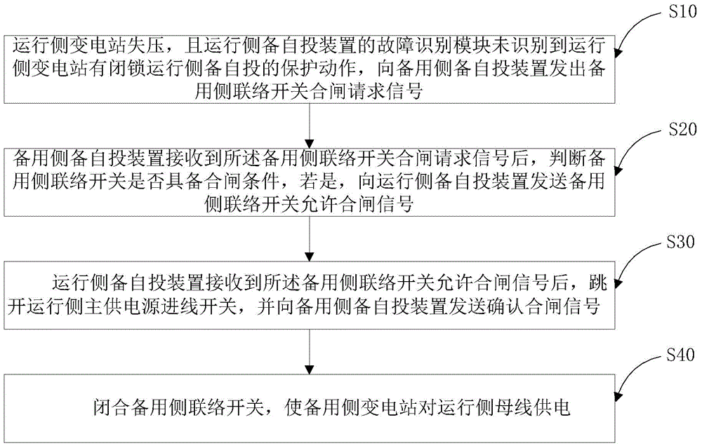
[0047] figure 1 It is a flowchart of a remote backup power automatic switching method provided by an embodiment of the present invention.

[0048] A remote standby power automatic switching method, comprising:

[0049] S10. The running-side substation loses voltage, and the fault identification module of the running-side standby automatic switching device does not recognize that the running-side substation has a protection action of blocking the running-side standby automatic switching, and sends a backup side contact switch closing to the standby side standby automatic switching device request signal;

[0050] S20. After receiving the closing request signal of the backup side contact switch, the backup side automatic switching device judges whether the backup side contact switch has the closing condition, and if so, sends the backup side contact switch to the running side backup automatic switching device to allow closing Signal;

[0051] S30. After receiving the allowable...

Embodiment 2

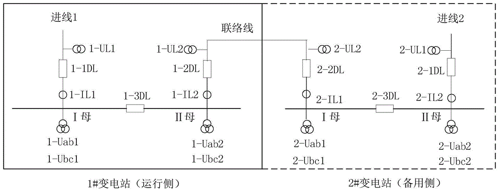
[0076] Such as figure 2 As shown, a remote backup power automatic switching system includes: a running side substation and a backup side substation, the running side substation and the backup side substation communicate through an optical fiber communication device, and the running side substation and the backup side substation A tie line is arranged between them, and the running side substation includes: running side main power supply incoming line switch 1-1DL, running side section switch 1-3DL, running side tie switch 1-2DL, running side I section busbar and Section II busbar; the substation on the standby side includes: main power supply incoming switch 2-1DL on the standby side, section switch 2-3DL on the standby side, contact switch 2-2DL on the standby side, busbar I and section II on the standby side .

[0077] In this embodiment, it also includes:

[0078] The main power supply incoming line voltage transformer 1-UL1 on the running side is used to detect the incom...


PUM


Abstract

The invention relates to relates to the technical field of electric power, and particularly relates to a remote backup power supply automatic switching method and system. The method comprises the steps that voltage loss occurs on an operation side transformer station and the fault identification module of an operation side backup power automatic switching device does not identify the protection action of the operation side transformer station for blocking operation side backup power automatic switching, and a backup side interconnection switch closing request signal is transmitted to a backup side backup power automatic switching device; the backup side backup power automatic switching device judges whether a backup side interconnection switch meets the closing condition, and a backup side interconnection switch closing allowing signal is transmitted to the operation side backup power automatic switching device if the judgment result is yes; an operation side main power supply incoming switch is tripped off by the operation side backup power automatic switching device, and a closing confirmation signal is transmitted to the backup side backup power automatic switching device; and the backup side interconnection switch is closed so that a backup side transformer station is enabled to supply power to an operation side bus. The remote backup power supply automatic switching method and system are suitable for the working conditions with interconnection wires between the transformer stations, and the functions of mutual backup between the transformer stations and remote automatic switching can be realized on the basis of an existing backup power automatic switching system so that compatibility is high and maintainability is high.

Description

technical field [0001] The invention relates to the technical field of electric power, in particular to a method and system for automatic switching of a remote backup power supply. Background technique [0002] With the development of urban and rural construction, users have higher and higher requirements for power supply reliability, which puts forward higher requirements for the quality of the original power supply and distribution equipment and the reliability of the power supply and distribution network. Most of the power supply network adopts radial power supply. This power supply method has many disadvantages. Once a fault occurs somewhere, it will cause a large-scale power outage on the entire line, and the power outage time is long and the reliability is poor. In order to change this situation, you can The inter-station tie line is set up between the two substations, which greatly improves the reliability of the power supply and distribution network. [0003] Domest...

Claims


Application Information

Patent Timeline
Patent Type & Authority Applications(China)
IPC IPC(8): H02J9/06H02J13/00
CPCY02B70/30Y02B90/20Y02E60/00Y04S10/16Y04S20/12Y04S20/20
Inventor 黄滇生许永军胡祖伟李蔚凡袁蓉姜超段宗佐杨文波芮平胡艳玲张静杨士俊徐飞
Owner DALI POWER SUPPLY BUREAU YUNNAN POWER GRID
Why Eureka
Try Eureka