Dog clutch control device for automatic transmission

A technology of claw clutches and automatic transmissions, which is applied in the direction of mechanical control devices, mechanical drive clutches, clutches, etc., can solve the problem that the sleeve and the idler gear cannot be engaged, and achieve the effect of fast shifting action and shortening the time

Inactive Publication Date: 2016-01-13
AISIN SEIKI KK
View PDF10 Cites 7 Cited by
  • Summary
  • Abstract
  • Description
  • Claims
  • Application Information

AI Technical Summary

Problems solved by technology

In addition, the sleeve and the idler gear may not engage well depending on the timing at which the sleeve is pressed against the idler gear.

Method used


Image

  • Dog clutch control device for automatic transmission
  • Dog clutch control device for automatic transmission
  • Dog clutch control device for automatic transmission

Examples


Embodiment 1

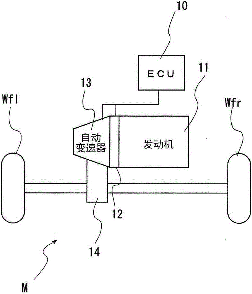
[0075] Next, a first embodiment in which an automatic transmission having the dog clutch control device for an automatic transmission of the present invention applied to a vehicle will be described with reference to the drawings. figure 1 It is a schematic diagram showing the structure of the above-mentioned vehicle.

[0076] Such as figure 1 As shown, the vehicle M includes an engine 11, a clutch 12, an automatic transmission 13, a differential device 14, and drive wheels (left and right front wheels) Wfl, Wfr. The engine 11 generates driving power by burning fuel. The driving force of the engine 11 is transmitted to drive wheels Wfl, Wfr via a clutch 12, an automatic transmission 13, and a differential device 14 (so-called FF vehicle).

[0077] The clutch 12 is automatically disengaged or engaged according to an instruction from a control unit (ECU) 10 . The automatic transmission 13 incorporates a dog clutch transmission mechanism, and automatically selects, for example,...

Embodiment 2

[0116] Next, a second embodiment in which an automatic transmission including the dog clutch control device for an automatic transmission of the present invention is applied to a vehicle will be described with reference to the drawings.

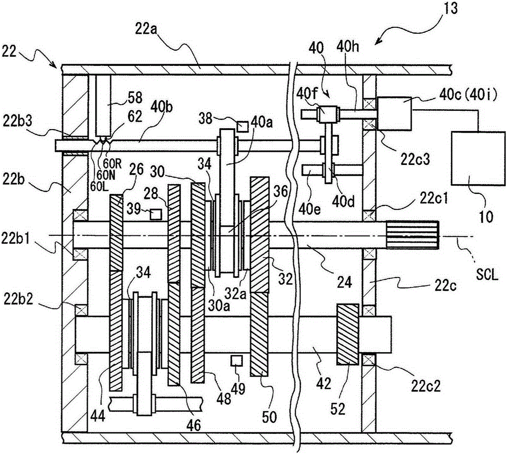
[0117]The shift pawl mechanism 58 of the dog clutch control device for an automatic transmission according to the present embodiment has a neutral positioning concave portion 60N for positioning the sleeve 36 at the neutral position and left and right meshing positioning concave portions for positioning the sleeve 36 at the meshing position. In addition to 60R and 60L, there are two stop positioning recesses 60SR and 60SL for stopping the high teeth 36a1 of the sleeve 36 in front of the front end surfaces 30b6 of the clutch rear teeth 30b2 of the third and fourth clutch rings 30 and 32, etc. This point is different from the first embodiment. Below, based on Figure 10 Give a detailed explanation. Since the other structures are the same, the...


PUM


Abstract

Provided is a dog clutch control device for an automatic transmission that makes it possible to perform a speedy shifting operation when, during shifting, a sleeve is moved and engaged with the dog clutch. A control device (10), which has a calculation unit (10b) for calculating the speed of movement of the sleeve (36) on the basis of the position detected at a predetermined time by a stroke position sensor (38) for detecting the position of movement of the sleeve (36), and which controls the operation of a shaft device (40) on the basis of the position detected by the stroke position sensor and the speed of movement of the sleeve, applies, after high teeth (36a1) of the sleeve have passed a chamfered portion (30b3) of clutch front teeth of the clutch ring (30), a stopping thrust load (F4) for stopping the forward movement of the high teeth before the high teeth come into contact with the end surfaces (30b6) of clutch back teeth (30b2) of the clutch ring.

Description

technical field [0001] The present invention relates to a control device for dog clutches used in automatic transmissions for vehicles. Background technique [0002] Conventionally, a powertrain of a vehicle has a transmission that converts torque and rotational speed in order to transmit rotation and torque from a driving device such as an engine or an electric motor used for driving to driving wheels according to driving conditions. There are several types of transmissions, but known, for example, are the following constant mesh type transmissions, that is, a plurality of idler gears that are fitted so as to be rotatable with respect to a rotating shaft connected to a drive wheel and cannot move in the direction of the rotating axis, and A plurality of gears arranged around an intermediate shaft whose rotation axes are arranged in parallel are always in mesh. In this transmission, a sleeve that is spline-fitted with the rotating shaft so as to be movable in the direction ...

Claims


Application Information

Patent Timeline
Patent Type & Authority Applications(China)
IPC IPC(8): F16H61/04F16H61/28F16H63/32
CPCF16H61/04F16D21/04F16D2011/006F16D2011/008F16H63/38F16H2061/0474F16H2061/2823
Inventor 森匡辅岩崎靖久吉田雄亮甲村雅彦岩田崇司
Owner AISIN SEIKI KK
Why Eureka
Try Eureka