
Processing method of thin-walled fan shell with holes and workpiece positioning tool

A processing method and thin-walled technology, applied in the direction of positioning devices, metal processing machinery parts, metal processing equipment, etc., can solve the problems of difficulty in stabilizing the forming accuracy of thin-walled parts, the influence of forming accuracy, and the complexity of the process, so as to achieve stable processing, Simple clamping and convenient use

Inactive Publication Date: 2017-05-17
TIANJIN UNIV OF COMMERCE
View PDF6 Cites 0 Cited by
  • Summary
  • Abstract
  • Description
  • Claims
  • Application Information

AI Technical Summary

Problems solved by technology

[0002] When precision instruments are running, thin-walled housings such as fans are required to cool down key components. In order to ensure the safe operation of the instrument and reduce the overall weight of expensive instruments, the fan housing is generally made of aluminum alloy precision casting. The whole process is generally Including complex processes such as mold design, wax mold processing, sand hanging, baking, casting, heat treatment, etc., the production cycle is long, the process is complicated, and the forming accuracy of thin-walled parts is difficult to stabilize. Body parts manufacturing, the process method is costly
If a general-purpose CNC machine tool is used to mill thin-walled shell parts, it is necessary to use a pressure plate to clamp the workpiece, which is easily deformed during processing and difficult to complete in one process, and its forming accuracy is also affected

Method used


Image

  • Processing method of thin-walled fan shell with holes and workpiece positioning tool
  • Processing method of thin-walled fan shell with holes and workpiece positioning tool
  • Processing method of thin-walled fan shell with holes and workpiece positioning tool

Examples


Embodiment Construction

[0031] The present invention will be described in further detail below in conjunction with the accompanying drawings and specific embodiments.

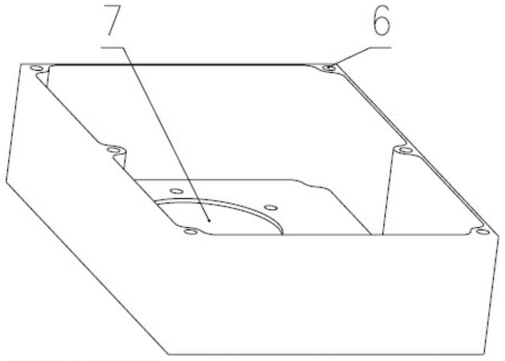
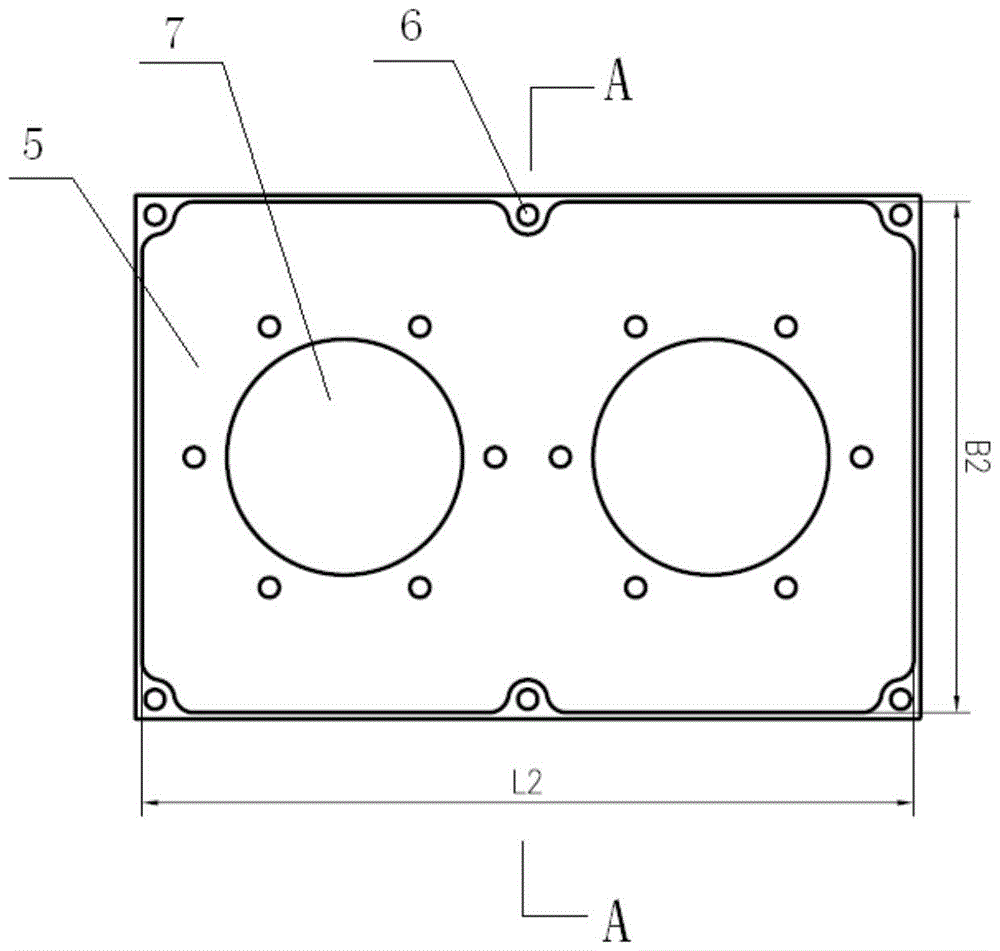
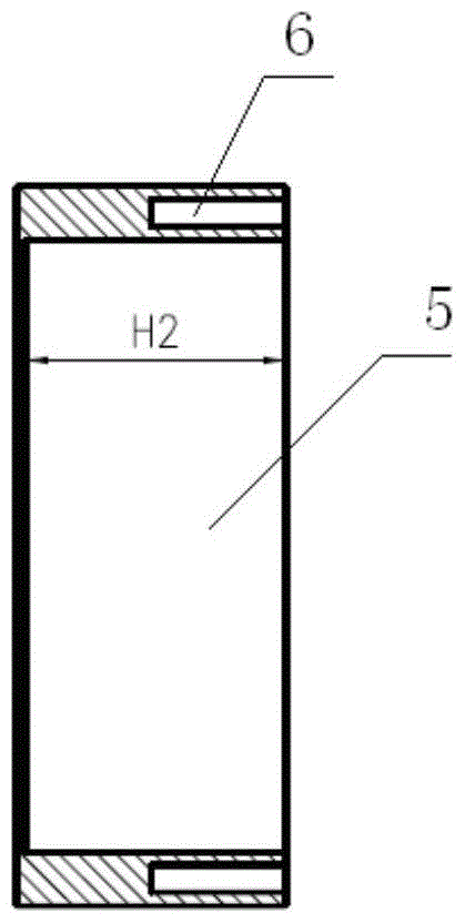
[0032] The schematic diagram of the workpiece positioning tool used in the processing method of the thin-walled fan casing with holes of the present invention is as follows Figure 5-Figure 7 shown. The tooling used in the processing method of the present invention comprises an integral base 9 and a support body 11, and grooves 12 are respectively arranged at positions opposite to the workpiece threaded holes of the support body 11, and the outer contour of the support body 11 is in line with the described support body 11. According to the shape corresponding to the workpiece cavity, threaded through holes are respectively arranged on the base 9 opposite to the workpiece threaded holes, and the screws 10 pass through the threaded through holes and are threadedly connected with the threaded holes on the workpiece. The upper surface 8 ...


PUM


Abstract

The invention discloses a machining method of porous thin-wall fan cases and a work-piece locating tool. The machining method of the porous thin-wall fan cases is high in machining efficiency and machining stability, and the tool is convenient to use. The machining method comprises the steps of roughly machining cavities of work-pieces; precisely machining the cavities of the work-pieces; machining threaded holes; roughly machining the peripheral contours of the work-pieces; uniformly coating the surface, making contact with the work-pieces, of the tool with fine gypsum powder with the thickness being 0.15 mm, slowly sleeving the tool with the cavities of the work-pieces and discharging the redundant gypsum powder between the tool and the work-pieces through the gap between the tool and the work-pieces; tensioning the work-pieces from the bottom surface of the tool through screws, and fixing the work-pieces through the friction force between the bottom surfaces of the work-pieces and the top surface of the tool; precisely machining the peripheral contours of the work-pieces; precisely machining the peripheral contours of the work-pieces again. By adopting the machining method, the clamping time of the work-pieces is shortened, machining deformation of thin-wall parts is controllable, the machining efficiency is high, and the machining stability of the thin-wall parts is improved.

Description

technical field [0001] The invention relates to the technical field of machining, and more specifically relates to a processing method for a thin-walled fan casing with holes and a workpiece positioning tool. Background technique [0002] When precision instruments are running, thin-walled housings such as fans are required to cool down key components. In order to ensure the safe operation of the instrument and reduce the overall weight of expensive instruments, the fan housing is generally made of aluminum alloy precision casting. The whole process is generally Including complex processes such as mold design, wax mold processing, sand hanging, baking, casting, heat treatment, etc., the production cycle is long, the process is complicated, and the forming accuracy of thin-walled parts is difficult to stabilize. Body parts manufacturing, the process method is costly. If a general-purpose CNC machine tool is used for milling thin-walled shell parts, the workpiece needs to be ...

Claims


Application Information

Patent Timeline
Patent Type & Authority Patents(China)
IPC IPC(8): B23C3/00B23Q3/06
Inventor 王勇张晓川王怀文马涛文黄嘉伟邓江彭东亭王小利方雅阁周亮张强其他发明人请求不公开姓名
Owner TIANJIN UNIV OF COMMERCE
Learn More