3D metal welding and printing method based on gas metal arc welding and numerical control machining

A technology of melting electrode gas and 3D printing, which is applied in the field of metal welding 3D printing and manufacturing metal parts, which can solve the problems of inability to manufacture high density and high strength, eliminate defects such as internal pores and microcracks, and increase cooling speed , Improve the effect of density

Active Publication Date: 2016-01-20
四川康铭智能装备科技有限公司
View PDF2 Cites 22 Cited by
  • Summary
  • Abstract
  • Description
  • Claims
  • Application Information

AI Technical Summary

Problems solved by technology

[0005] The purpose of the present invention is to provide a metal welding 3D printing method based on gas metal shielded welding and numerical control machining, to solve the p

Method used


Image

  • 3D metal welding and printing method based on gas metal arc welding and numerical control machining
  • 3D metal welding and printing method based on gas metal arc welding and numerical control machining
  • 3D metal welding and printing method based on gas metal arc welding and numerical control machining

Examples


Embodiment 1

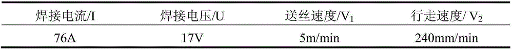
[0023] This example uses ER50-6 solid core welding wire for welding hollow objects with a single wall thickness of 3mm and a size of 80mm×80mm×60mm. The shielding gas uses Ar80%+CO 2 20% mixed gas. One weld on each layer, the height of each weld is 3mm, and the distance between adjacent welds (the upper and lower layers) is 3mm. The lowering height of the working table is 3mm, the surface of the obtained welding sample is well formed, the bonding effect between the upper and lower adjacent welds is better, and there is no obvious boundary in the macroscopic view. The specific welding process parameters are shown in the following table:

[0024] Process parameters of the bottom 1-4 layers of the sample

[0025]

[0026] Process parameters of the middle 5-15 layers of the sample

[0027]

[0028] Process parameters of the top 16-20 layers of the sample

[0029]

[0030] Due to the small size of the sample, it did not meet the requirements of the national standard, and it was not test...

Embodiment 2

[0032] This example uses The ER50-6 welding wire is used for welding hollow samples, the size is 350mm×60mm×45mm. Shielding gas is mixed gas: Ar80%+CO 2 20%. Each layer consists of 5 welds. The width of each weld is w=3mm, and the height h=3mm. The distance between adjacent welds (two meanings: one means adjacent to each other up and down; one means adjacent to left and right) is 3mm. The lowering height of the worktable is 3mm, the surface of the welded sample prepared is well formed, the bonding effect between the two welds is good, and there is no obvious boundary in the macroscopic view. The specific welding process parameters are shown in the following table:

[0033] Process parameters of the bottom 1-5 layers of the sample

[0034]

[0035] Process parameters of the middle 6-8 layers of the sample

[0036]

[0037] Process parameters of the top 9-15 layers of the sample

[0038]

[0039] Sample mechanical performance testing

[0040]

[0041] In short, the present invention ...


PUM

PropertyMeasurementUnit
Diameteraaaaaaaaaa

Abstract

The invention discloses a 3D metal welding and printing method based on gas metal arc welding and numerical control machining. A fusion welding machine serves as a welding heat source, 3D printing equipment serves as a moving device and a numerically-controlled machine tool machines forming surfaces. Accumulated errors and defects possibly generated internally are eliminated by adopting Z-shaped scanning and rotating each layer by a certain angle. Bead welding is carried out through the one pulse-one droplet globular transfer mode, the numerically-controlled machine tool immediately machines the surface of deposited metal once a layer of the deposited metal is accumulated, the welding process property of obtained sample pieces is excellent, and the strength of the deposited metal can meet the industrial use requirement.

Description

Technical field [0001] The invention belongs to the technical field of 3D printing equipment and material processing, and relates to a metal welding 3D printing method based on a combination of MIG welding and numerical control processing, which is used for manufacturing metal parts. Background technique [0002] 3D printing technology is the main realization form of RPM. The materials are stacked regularly and accurately to form a three-dimensional entity. Its biggest advantage is that it can simplify manufacturing procedures, increase product molding speed, shorten the development cycle of new products, and reduce development costs and risks. Manufacturing metal parts is the most cutting-edge and most promising technology in 3D printing technology, and an important development direction of advanced manufacturing technology. At present, 3D printing can manufacture metal parts mainly including: selective printing forming, welding printing forming, droplet printing forming and we...

Claims


Application Information

Patent Timeline
IPC IPC(8): B23K9/173B23K9/04B23K9/32
CPCB23K9/04B23K9/173B23K9/32
Inventor 杨建森邢奎王永信
Owner 四川康铭智能装备科技有限公司
Why Eureka
Try Eureka