
Explosive column for smooth blasting excavation of foundation surface and excavation technology

A technology for building a foundation surface and explosives, applied in blasting and other directions, can solve the problems of limited blasting shock wave buffering effect, large amount of manual prying, low construction efficiency, etc. Effect

Active Publication Date: 2016-01-20
SINOHYDRO BUREAU 16 CO LTD +1
View PDF5 Cites 2 Cited by
  • Summary
  • Abstract
  • Description
  • Claims
  • Application Information

AI Technical Summary

Problems solved by technology

In the prior art, the construction efficiency of the traditional deep hole step blasting is often very low, and the damage to the rock mass retained at the bottom of the hole is relatively large; the horizontal pre-splitting or horizontal smooth surface blasting has good excavation effect, but the construction efficiency is still not enough. satisfactory
In recent years, the sequential detonation method between holes in small steps with a flexible cushion at the bottom of the hole, due to the limited cushioning effect of the flexible cushion material on the blasting shock wave, the damage to the bottom of the hole is still relatively large, and the excavated foundation surface has a large fluctuation difference , resulting in a large amount of manual prying and excavation; at the same time, the ordinary energy-concentrating blasting using a wedge-shaped charge tank cannot achieve ideal results due to the limited energy-concentrating effect of the device.

Method used


Image

  • Explosive column for smooth blasting excavation of foundation surface and excavation technology
  • Explosive column for smooth blasting excavation of foundation surface and excavation technology
  • Explosive column for smooth blasting excavation of foundation surface and excavation technology

Examples


Embodiment Construction

[0029] The present invention will be further described below with reference to the accompanying drawings and specific embodiments.

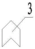
[0030] like figure 1 , 2 As shown, a kind of explosive column used for blasting and excavation of foundation surface, which comprises rows of vertical blastholes 8 that are located in the center of the rock mass, a buffer layer 4, a rigid cushion layer 3, a buffer layer 4 at the bottom of the blasthole holes, Explosive 2, blocking section 1, buffer layer 4, rigid cushion 3, explosive 2, blocking section 1 are stacked in order from bottom to top. The buffer layer 4 is a cylinder, the diameter of which is smaller than the diameter of the blasting hole by 0.5-1 cm, so that it can be put into the blasting hole smoothly, and the height of the buffer layer 4 is 10-40 cm. The thickness of the buffer layer laid in each blast hole is the same, and the buffer layer is made of foamed concrete.

[0031] The upper and lower surfaces of the rigid cushion la...


PUM


Abstract

The invention discloses an explosive column for smooth blasting excavation of a foundation surface and an excavation technology. The explosive column is characterized by comprising blast holes, a buffering layer, a rigid cushion layer, an explosive and a plugging segment, wherein the buffering layer, the rigid cushion layer, the explosive and the plugging segment are arranged at the bottoms of the blast holes; and the buffering layer, the rigid cushion layer, the explosive and the plugging segment are sequentially stacked from bottom to top. The buffering layer is a cylinder; the diameter of the buffering layer is smaller than the diameter of each blasting hole by 0.5 cm-1 cm, and the upper surface and the lower surface of the rigid cushion layer are both conical; and the upper surface and the lower surface of the rigid cushion layer are parallel to each other, and therefore the two-way energy gathering effect can improved. When the explosive column is used, the vertical blast holes, with the circle centers collinear, in rows are drilled in a rock body, and the buffering layer, the rigid cushion layer, the explosive and the plugging segment are sequentially stacked from bottom to top. The technology is simple and convenient, cost is low, operation is easy, adverse effects are reduced because of the two-way energy gathering effect of the rigid cushion layer, the excavation effect is reliable, it can be guaranteed that the dam foundation surface and a slope packway protective layer are formed at a time through excavation, and the explosive column is widely used for excavation engineering of foundation surfaces and slope protective layers of the industries of water conservancy and hydropower engineering, transportation and mines.

Description

technical field [0001] The invention belongs to the technical field of engineering blasting, in particular to a rigid-flexible composite cushion used for blasting and excavating a foundation surface. Background technique [0002] The forming control of the contour surface is an important indicator of the blasting effect. The excavation quality of the foundation surface of the hydropower project and the protective layer of the slope horse road has always been a difficult point in the construction of the hydropower project. In the prior art, the traditional deep hole bench blasting often has low construction efficiency and relatively large damage to the rock mass retained at the bottom of the hole; horizontal pre-splitting or horizontal smooth blasting, the excavation effect is still good, but the construction efficiency is still insufficient. Satisfactory. In recent years, the sequential detonation method of small ladder sections with flexible cushion at the bottom of the h...

Claims


Application Information

Patent Timeline
Patent Type & Authority Applications(China)
IPC IPC(8): F42D1/00F42D1/08F42D3/04
Inventor 郑昌莹黎卫超吴秀荣胡英国李绍辉李鹏李琦
Owner SINOHYDRO BUREAU 16 CO LTD
Learn More