Giant magneto-resistance sensor differential drive and magnetic field bias circuit and bias method

A giant magnetoresistance and differential drive technology, applied in instruments, measuring devices, measuring magnetic variables, etc., to reduce complexity and save power modules

Active Publication Date: 2016-01-20
ZHUZHOU YIXING TECH CO LTD
View PDF10 Cites 6 Cited by
  • Summary
  • Abstract
  • Description
  • Claims
  • Application Information

AI Technical Summary

Problems solved by technology

[0008]So although these above-mentioned patents all relate to the sensor of giant magnetoresistance and its application, and all do to giant magnetoresistance sensor or the method that utilizes giant magnetoresistance sensor to detect However, there are no suggestions on how to improve the giant magnetoresistance sensor to maintain accurate detection performance in a strong magnetic field environment. Therefore, under a strong magnetic field, the giant magnetoresistance sensor is often magnetized by an external magnetic field. However, the problem of affecting the detection accuracy still exists. At the same time, the signal detected by the sensor will be affected by environmental parameters such as external temperature, and the signal transmitted by the magnetic sensor is prone to distortion, which still needs to be further improved.

Method used


Image

  • Giant magneto-resistance sensor differential drive and magnetic field bias circuit and bias method
  • Giant magneto-resistance sensor differential drive and magnetic field bias circuit and bias method

Examples


Embodiment 1

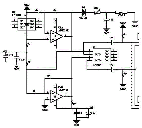
[0027] Such as figure 1 Shown in: a giant magnetoresistance sensor differential drive and magnetic field bias circuit, including two op amps, the input power is input to a negative pole and a positive pole of the two op amps after passing through the power reference module, so that the two The op amp generates stable and amplified positive and negative voltages, and the two op amps are respectively connected to the positive and negative power terminals of the giant magnetoresistance sensor as the driving voltage for the giant magnetoresistance chip; one of the op amps outputs the diode, An adjustable resistor and a decoupling capacitor are connected to one end of the coil, and the other end of the coil is grounded. By adjusting the adjustable resistor, the current passing through the coil is changed, thereby generating a variable bias magnetic field.

[0028] The two operational amplifiers are respectively the first operational amplifier U1A and the second operational amplifier...


PUM


Abstract

The invention discloses a giant magneto-resistance sensor differential drive and magnetic field bias circuit and a bias method. The circuit comprises two operational amplifiers; input power passes through a power reference module and is then inputted to one negative electrode and one positive electrode of the two operational amplifiers respectively to enable the two operational amplifiers to generate stable and amplified positive and negative voltage, and the two operational amplifiers are connected with the positive power end and the negative power end of the giant magneto-resistance sensor respectively to serve as drive voltage of a giant magneto-resistance chip; and output of one operational amplifier passes through a diode, an adjustable resistor and a decoupling capacitor at the same time to be connected to one end of a coil, and the other end of the coil is grounded. Through adjusting the adjustable resistor, current passing through the coil is changed, and a changeable bias magnetic field is thus generated.

Description

technical field [0001] The present invention relates to a sensor drive method and circuit, in particular to a giant magnetoresistance sensor differential drive and magnetic field bias circuit and bias method, the giant magnetoresistance sensor differential drive and magnetic field bias circuit and bias method is a sensor It provides a stable differential power supply and provides additional amplification for the output of the sensor; the external bias magnetic field can adjust the operating point of the sensor, so that the sensor can output bipolar signals. It belongs to the field of sensor technology. [0002] Background technique: [0003] Due to its small size, high sensitivity, easy installation, and high three-axis vertical accuracy, the giant magnetoresistance effect magnetic field sensor is used for detection. In the field of magnetic field detection with space restrictions and pointing requirements, the giant magnetoresistance effect magnetic field sensor is a very ...

Claims


Application Information

Patent Timeline
Patent Type & Authority Applications(China)
IPC IPC(8): G01R33/09
Inventor 谢成昆彭晓靖
Owner ZHUZHOU YIXING TECH CO LTD
Why Eureka
Try Eureka