Insulated residual cable stand

A technology for residual cable racks and residual cables, which is applied in the field of insulating residual cable racks, can solve the problems of increased accident hazards, personnel strength, rubber aging, and insulation performance decline, and achieves the advantages of easy portability and transportation, good aging resistance, and beautiful appearance Effect

Inactive Publication Date: 2016-01-20
STATE GRID CORP OF CHINA +1
View PDF5 Cites 8 Cited by
  • Summary
  • Abstract
  • Description
  • Claims
  • Application Information

AI Technical Summary

Problems solved by technology

The original insulation method is to use insulating rubber to isolate the conduction of current. Since the insulating rubber is tightly pressed on the pole by the steel belt hoop, it is very easy to cause rubber aging, resulting in a decline in insulation performance. It needs to be replaced regularly, which increases the Accident hazards and personnel intensity

Method used


Image

  • Insulated residual cable stand
  • Insulated residual cable stand
  • Insulated residual cable stand

Examples


Embodiment Construction

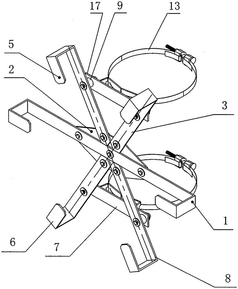
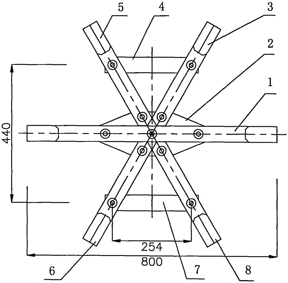
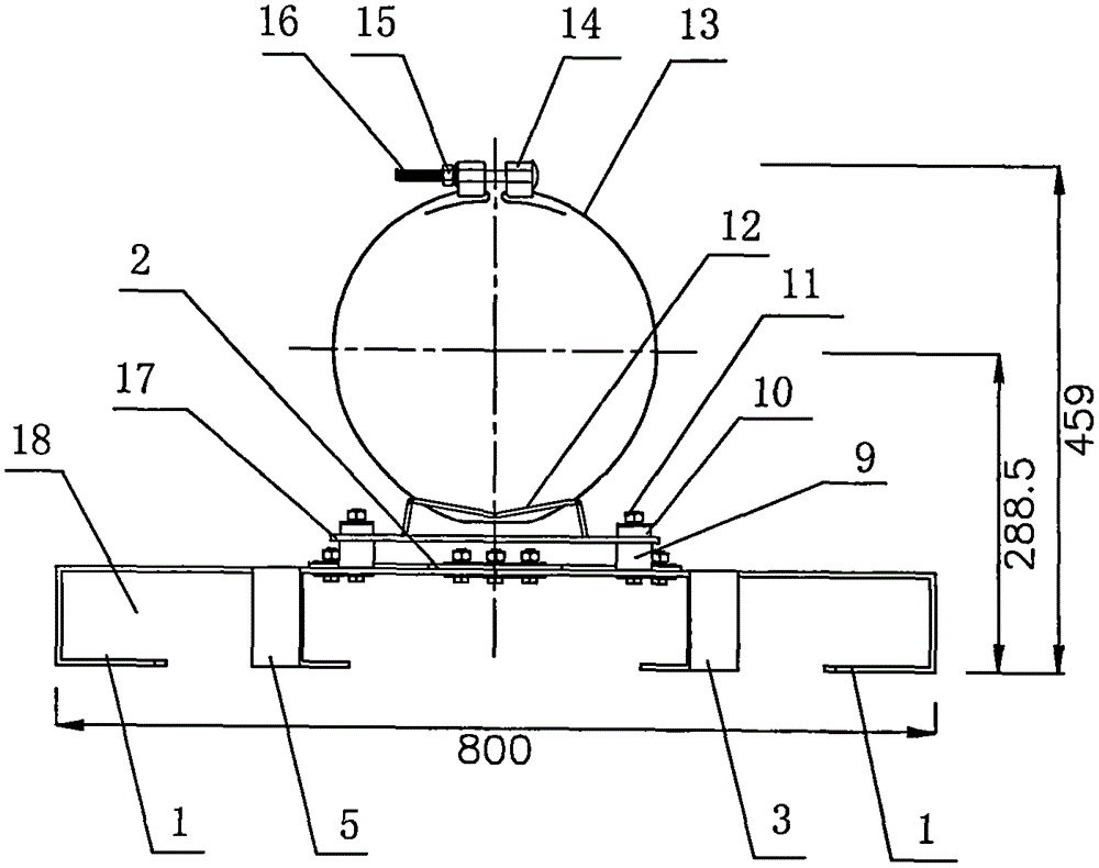
[0031] Such as Figure 1-11 Shown, a kind of insulated remaining cable rack, it comprises remaining cable rack disc, first steel band hoop fixing device 4, second steel band hoop fixing device 7, insulation device; first steel band hoop fixing device 4, The second steel band hoop fixing devices 7 are respectively insulated and connected to the remaining cable racks through insulating devices.

[0032] Described remaining cable tray comprises long support 1, the first short support 3, the second short support 5, the 3rd short support 6, the 4th short support 8, connecting plate 2; The middle part of long support 1 and connecting plate 2 pass bolt connection (the long bracket and the connecting plate are all provided with holes for bolt connection), and the two ends of the long bracket 1 are respectively bent forward into a U-shaped mouth 18 ( figure 1 The middle face of the viewer is in front, that is figure 2 The lower part is the front, figure 2 The top of the top is the...


PUM


Abstract

The invention relates to an insulated residual cable stand and mainly used in optical communication field in an optical fiber composite overhead ground wire (OPGW) high-voltage transmission line. The insulated residual cable stand is characterized by comprising a residual cable stand disc, a first steel belt hoop fixing device, a second steel belt hoop fixing device, and an insulating device. The first steel belt hoop fixing device and the second steel belt hoop fixing device are in insulated connection with the residual cable stand disc and have same structure. Each of the first steel belt hoop fixing device and the second steel belt hoop fixing device has a steel belt hoop, an M iron plate, and a fixing plate. The M iron plate is in an M shape and both ends of the M iron plate are fixed to the fixing plate. Both side surfaces of the M iron plate are provided with steel belt passing holes. The steel belt of the steel belt hoop passes through the steel belt passing holes on both side surfaces of the M iron plate. The insulating device comprises an insulated sleeve, an insulated plug, and a fixing bolt. The insulated residual cable stand has a reliable insulating property, may adapt to the requirements of different rod diameters, and can be well and stably fixed to an electric pole.

Description

technical field [0001] The invention relates to an insulating residual cable rack (insulating fitting), which is mainly used in the field of optical communication in optical fiber composite overhead ground wire (OPGW) high-voltage transmission lines. Background technique [0002] When the ground wire is insulated, the method of increasing the ground point can be used to reduce the short-circuit current in the OPGW. In the line with OPGW, OPGW and shunt line are required to be grounded tower by tower to accelerate the attenuation of short-circuit current. In the long line, some will be far away from the ground wire of the substation, and the ground insulation will be used to reduce power consumption. When the line is short-circuited in the insulation section, the short-circuit current returns to the substation through only one OPGW. At this time, the short-circuit current in the OPGW will suddenly increase, which may be greater than the allowable value. In order to reduce t...

Claims


Application Information

Patent Timeline
Patent Type & Authority Applications(China)
IPC IPC(8): H02G7/22
Inventor 陈维杜丰夷朱佳丁剑王浩曾聪
Owner STATE GRID CORP OF CHINA
Why Eureka
Try Eureka