Switching reluctance motor driving mechanism based on three-level inverter and control method thereof
A switched reluctance motor, three-level inverter technology, applied in the direction of AC motor control, control system, electrical components, etc., can solve the problems of not being able to adapt to different working states, restricting control flexibility, and being unable to adjust in real time. The effect of improving safety and reliability, reducing the difficulty of selection, and reducing costs
- Summary
- Abstract
- Description
- Claims
- Application Information
AI Technical Summary
Problems solved by technology
Method used
Image

Examples
Embodiment Construction
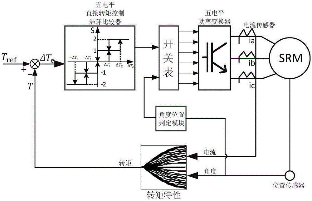
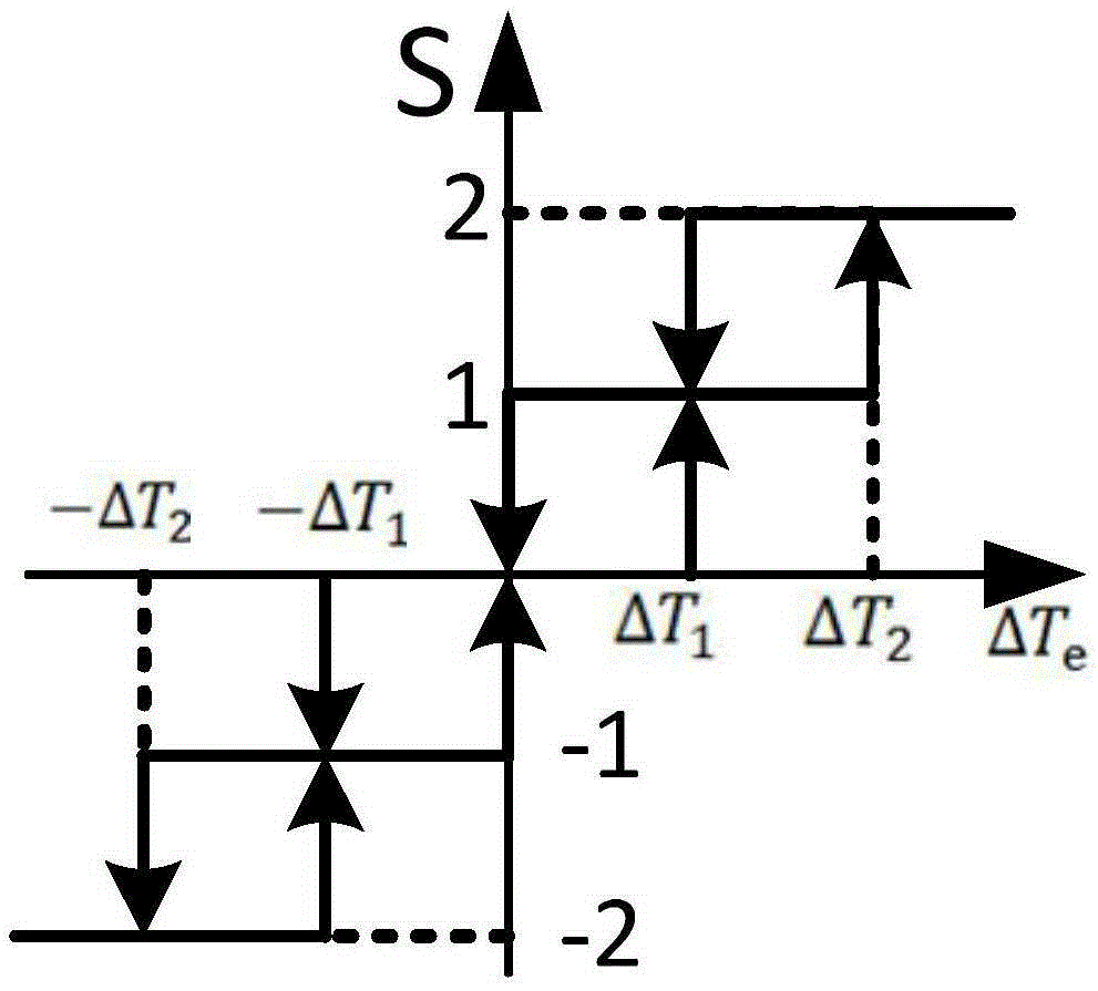
[0063] Combine below figure 1 and image 3 Illustrate the specific embodiment of the present invention:
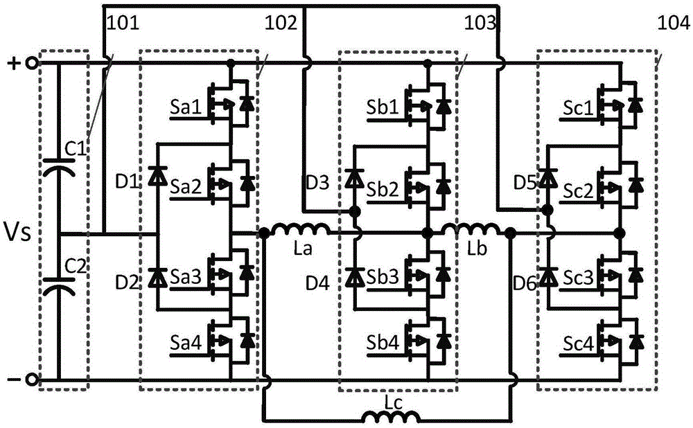
[0064] The driving structure of a switched reluctance motor based on a three-level inverter described in this embodiment is as follows: figure 1 As shown, it includes a power supply Vs, a switched reluctance motor phase A winding La, a switched reluctance motor phase B winding Lb, a switched reluctance motor phase C winding Lc, a capacitor module 101, a first bridge arm 102, and a second bridge arm 103 , the third bridge arm 104;
[0065] Figure 1 ~ Figure 3 The middle symbols respectively represent: Vs is the input power supply, which is the main power supply for the motor; Sa1, Sa2, Sa3, and Sa4 are the four switching tubes with anti-parallel diodes of the first bridge arm 102; Sb1, Sb2, Sb3, and Sb4 are Four switch tubes with anti-parallel diodes in the second bridge arm 103; Sc1, Sc2, Sc3, Sc4 are four switch tubes with anti-parallel diodes in the third bridge arm...
PUM
 Abstract
Description
Claims
Application Information
PatSnap Eureka turns technology decisions into work you can execute. Powered by our Innovation Knowledge Graph, it runs expert workflows across engineering, life sciences, materials and intellectual property. Get your review-ready output in minutes.


