RF Radio frequency transceiver, electronic device and method for adjusting work frequency band

A technology for radio frequency transceivers and electronic equipment, which is applied in the electronic field and can solve the problems of no multi-mode solution, high power consumption, and large circuit crosstalk.

Active Publication Date: 2016-01-20
LENOVO (BEIJING) CO LTD
View PDF6 Cites 14 Cited by
  • Summary
  • Abstract
  • Description
  • Claims
  • Application Information

AI Technical Summary

Problems solved by technology

[0004] In the prior art, multi-mode electronic equipment has a multi-mode multi-standby form and a multi-mode single-standby form. The multi-mode multi-band requires two baseband processors and two sets of radio frequency transceivers to work and standby at the same time, so the power consumption is relatively high. ;Multi-mode single standby can only have one baseband processor, but the radio frequency transceiver still needs multiple sets, and it needs the support of FallBack (rollback) from one network mode to another network mode on the network side
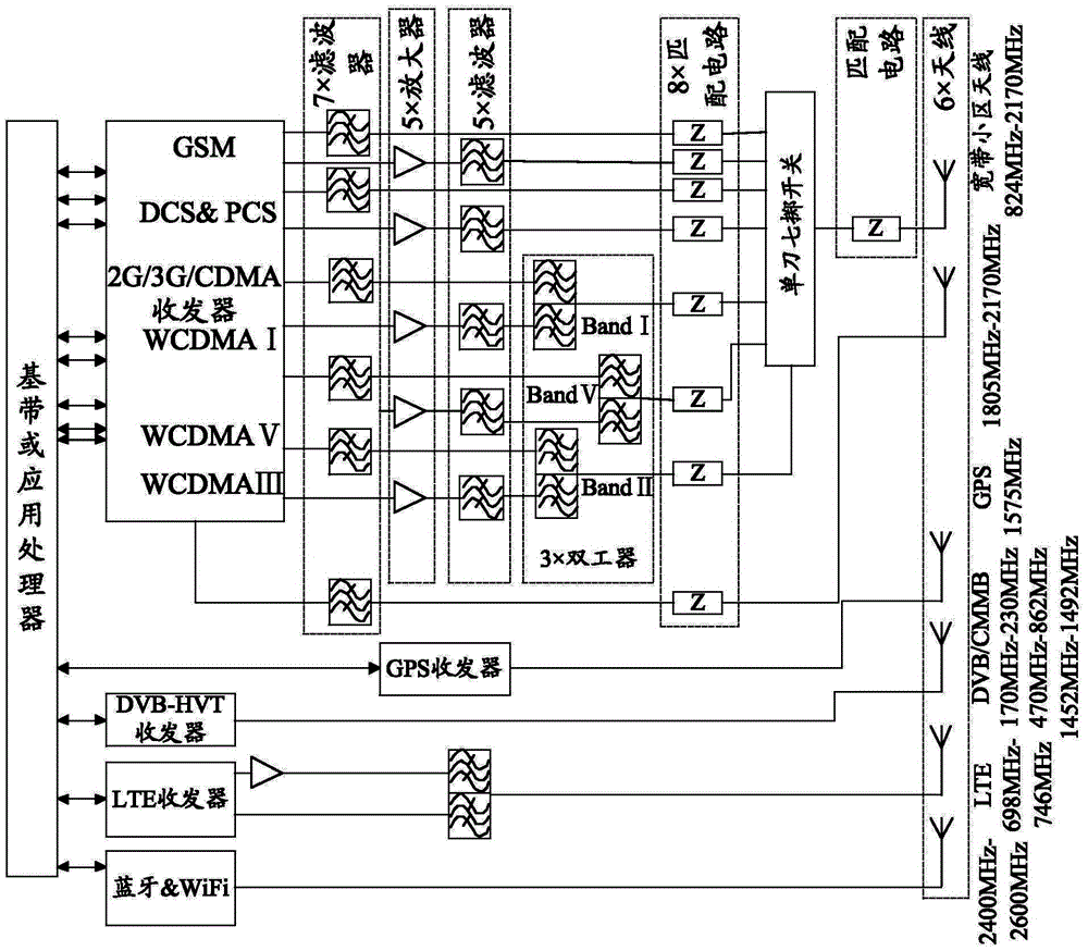
There is also a multi-mode electronic device with multiple transceivers, multiple RF front-end links, a large number of filters, amplifiers, matching circuits and switches, please refer to figure 1 As shown, it is a circuit structure diagram of a multi-mode mobile phone in the prior art. Multiple radio frequency devices are deployed on both sides of the PCB (printed circuit board), and the crossing of power signal lines occupies a large area, and multiple filters are required. device, so the circuit is complex and the circuit crosstalk is large
[0005] It can be seen from the above description of the prior art that there is no better multi-mode solution in the prior art

Method used


Image

  • RF Radio frequency transceiver, electronic device and method for adjusting work frequency band
  • RF Radio frequency transceiver, electronic device and method for adjusting work frequency band
  • RF Radio frequency transceiver, electronic device and method for adjusting work frequency band

Examples


Embodiment Construction

[0030] Embodiments of the present invention provide a radio frequency transceiver, electronic equipment and a method for adjusting a working frequency band, so as to solve the technical problem in the prior art that there is no better multi-mode solution.

[0031] The technical solution in the embodiments of the present invention is to solve the above-mentioned technical problems, and the general idea is as follows:

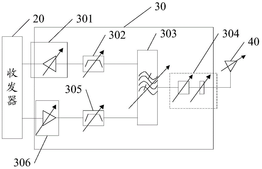
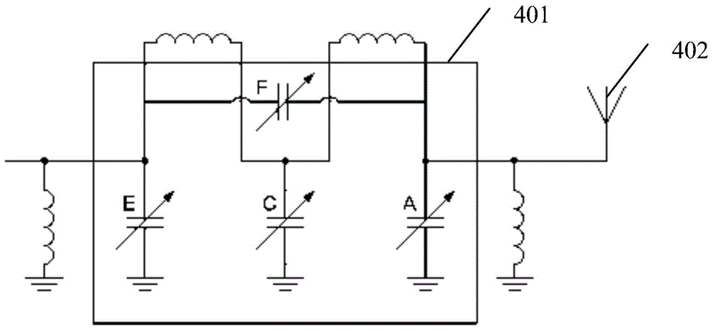
[0032] An embodiment of the present invention provides a radio frequency transceiver, including: an antenna with an adjustable frequency; a transceiver; a radio frequency front-end circuit with an adjustable frequency, connected between the antenna and the transceiver; mode and / or frequency band to generate uplink radio frequency signals, the network mode and frequency of the antenna and radio frequency front-end circuit can be adjusted to the current network mode and / or frequency band, the uplink radio frequency signal is transmitted through the antenna after bei...


PUM


Abstract

The invention provides a radio frequency transceiver, an electronic device and a method for adjusting a work frequency band. The radio frequency transceiver comprises an antenna with an adjustable frequency, a transceiver, and a radio frequency front-end circuit which has an adjustable frequency and is connected between the antenna and the transceiver, wherein the transceiver is used for generating an uplink radio frequency signal based on a current network mode and/or a current frequency band; the network mode and the frequency of both the antenna and the radio frequency front-end circuit can be adjusted into the current network mode and/or the current frequency band; the uplink radio frequency signal after being processed by the radio frequency front-end circuit is transmitted out through the antenna; the antenna is also used for obtaining a downlink radio frequency signal; the downlink radio frequency signal after being processed by the radio frequency front-end circuit reaches to the transceiver; and the transceiver is also used for processing the downlink radio frequency signal.

Description

technical field [0001] The invention relates to the field of electronic technology, in particular to a radio frequency transceiver, electronic equipment and a method for adjusting working frequency bands. Background technique [0002] With the development of communication technology, a variety of communication systems (also known as modes) have emerged, such as GSM (Global System for Mobile Communications; Global System for Mobile Communications), WCDMA (Wideband Code Division Multiple Access; Wideband Code Division Multiple Access) system, LTE (Long Term Evolution; long-term Evolution) system, in which GSM belongs to 2G (second generation) communication technology, WCDMA system belongs to 3G (third generation) communication technology, and LTE belongs to 4G (fourth generation) communication technology. Further, each communication system includes multiple frequency bands. At present, there are multiple frequency bands in the world. For example: GSM, the working frequency ban...

Claims


Application Information

Patent Timeline
Patent Type & Authority Applications(China)
IPC IPC(8): H04B1/38H04W88/06
Inventor 颜罡
Owner LENOVO (BEIJING) CO LTD
Why Eureka
Try Eureka