A kind of dummy shaft hydraulic press

A technology of hydraulic press and dummy shaft, which is applied to presses, forging presses, forging presses, etc., can solve the problems of insufficient working range, low working efficiency, and small working stroke, so as to improve the working scope, high working efficiency, and improve working stroke. Effect

Active Publication Date: 2017-08-25
HEFEI METALFORMING MACHINE TOOL
View PDF4 Cites 0 Cited by
  • Summary
  • Abstract
  • Description
  • Claims
  • Application Information

AI Technical Summary

Problems solved by technology

In the prior art, the dummy shaft returned by the dummy shaft hydraulic machine just falls into the pit, and then manually goes down to the pit to take out the dummy shaft and lift it away, which wastes a lot of time, so the work efficiency is very low. At the same time, the existing dummy shaft removal The hydraulic press has the disadvantages of small working stroke and insufficient working range

Method used


Image

  • A kind of dummy shaft hydraulic press
  • A kind of dummy shaft hydraulic press

Examples


Embodiment Construction

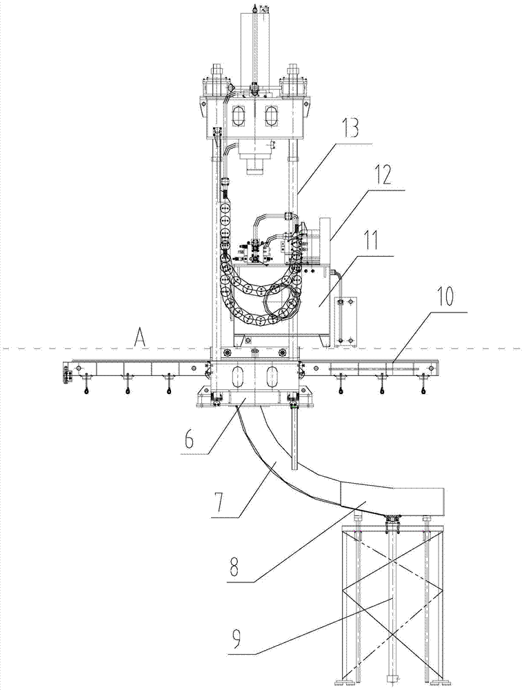
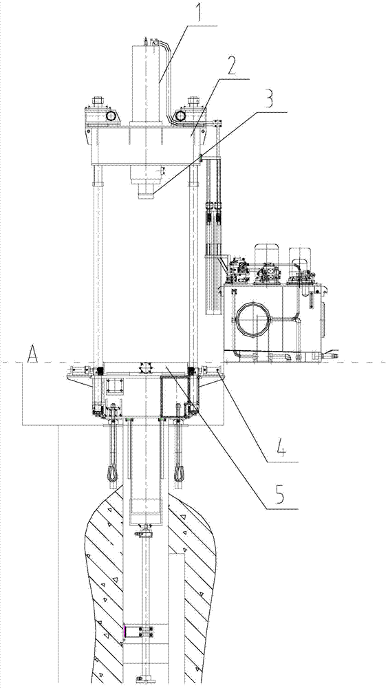
[0021] Such as Figure 1-2 as shown, figure 1 It is a schematic diagram of the front view structure of a hydraulic press for withdrawing false shafts proposed by the present invention; figure 2 It is a side-view structure schematic diagram of a false shaft retraction hydraulic press proposed by the present invention.

[0022] refer to figure 1 and figure 2 , a hydraulic machine for removing false shafts proposed by the present invention, comprising a main oil cylinder 1, a pressure head 3, two mobile trolley positioning mechanisms 4, a slide table type mobile trolley 5, a blanking slideway 7, a hopper 8, a material jacking mechanism 9, Front and rear guide rails 10 of the trolley, hydraulic power system 11, electrical system 12 and frame;

[0023] The frame includes a lower crossbeam 6, a movable upper crossbeam 2 and a pull rod 13, the pull rod 13 is vertically fixed on the lower crossbeam 6, and the movable upper crossbeam 2 is movably installed on the pull rod 13;

...


PUM


Abstract

The invention provides a dummy shaft withdrawing hydraulic press. The dummy shaft withdrawing hydraulic press comprises a main oil cylinder, a pressure head, two moving trolley positioning mechanisms, a sliding table type moving trolley, a falling slide, a receiving hopper, a jacking mechanism, front and back trolley guide rails, a hydraulic power system, an electrical system and a frame; the frame comprises a lower cross beam, a movable upper cross beam and a pull rod; the movable upper cross beam is movably mounted on the pull rod; the main oil cylinder is mounted on the movable upper cross beam; a piston rod of the main oil cylinder is in driving connection with the pressure head and the pressure head is driven by the main oil cylinder to move in a vertical direction; the pressure head is located between the movable upper and lower cross beams; a falling guiding square hole penetrating up and down is formed in the lower cross beam and a falling hole is formed in the sliding table type moving trolley; the falling guiding square hole communicates with the receiving hopper through the falling slide; the jacking mechanism is located below the receiving hopper and driving the receiving hopper to move in the vertical direction. The dummy shaft withdrawing hydraulic press has the advantages of large working travel and high working efficiency.

Description

technical field [0001] The invention relates to the technical field of forging machinery, in particular to a hydraulic press for removing false shafts. Background technique [0002] The dummy shaft hydraulic press is a special production equipment for motor low-pressure cast aluminum dummy shaft removal, and it can also be used for the correction, press-fitting and other pressing processes of other metal materials. One press can complete a series of actions such as moving in the cast aluminum rotor of this type of product, cutting off the dummy shaft, pressing out the dummy shaft, blanking, receiving, ejecting, and lifting the rotor and dummy shaft at the same time. In the prior art, the dummy shaft returned by the dummy shaft hydraulic machine just falls into the pit, and then manually goes down to the pit to take out the dummy shaft and lift it away, which wastes a lot of time, so the work efficiency is very low. At the same time, the existing dummy shaft removal The hydr...

Claims


Application Information

Patent Timeline
Patent Type & Authority Patents(China)
IPC IPC(8): B21J9/02B30B15/04B30B15/32
CPCB21J9/02B30B15/04B30B15/32
Inventor 时佩林曹玉
Owner HEFEI METALFORMING MACHINE TOOL
Why Eureka
Try Eureka