
Main shaft and balance mechanism of digital display type radial drilling machine

A technology of balance mechanism and radial drilling machine, which is applied in the direction of large fixed members, metal processing machinery parts, maintenance and safety accessories, etc. It can solve the problems of poor limit function, backward control system, and difficult to realize, and achieve complete functions and reliability. Advanced control system, simple and reasonable structure

Inactive Publication Date: 2016-01-27
SHENYANG JINGHONG NUMERICAL CONTROL EQUIP CO LTD
View PDF6 Cites 0 Cited by
  • Summary
  • Abstract
  • Description
  • Claims
  • Application Information

AI Technical Summary

Problems solved by technology

[0003] There are still many deficiencies in the spindle and balance mechanism of the radial drilling machine. The limit function of the upper and lower limits of the spindle and the balance mechanism is poor, the guiding accuracy of the guide rail is poor, the control system is relatively backward, some operations are difficult to realize, the structure is more complicated, and the operation is inconvenient. Low efficiency, high cost, high failure rate, low strength and rigidity, low transmission accuracy, short service life, time-consuming and laborious, high failure rate

Method used


Image

  • Main shaft and balance mechanism of digital display type radial drilling machine

Examples


Embodiment Construction

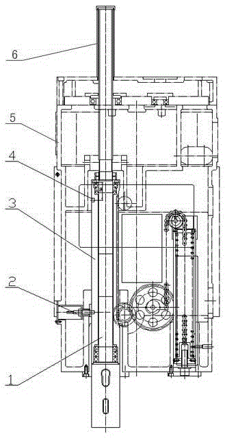
[0011] Referring to the attached drawings, a digital display type radial drilling machine main shaft and balance mechanism, including main shaft 1, proximity switch 2, main shaft sleeve 3, non-ferromagnetic material induction block 4, gearbox 5, spline sleeve 6, in the gearbox A proximity switch 2 is set on 5, a main shaft sleeve 3 is set on the bearing of the main shaft 1, a non-ferromagnetic material sensing block 4 is installed on the main shaft sleeve 3, and a spline sleeve 6 is installed on the upper part of the main shaft 1.

[0012] The working principle of the spindle and balance mechanism of a digital radial drilling machine is that a non-ferromagnetic material induction block 4 is installed in the hole on the spindle sleeve 3. When the proximity switch 2 of the spindle 1 moves to the non-inductive block 4. The generator signal realizes the limit function of the upper and lower limits of the main shaft and the balance mechanism. The vertical layout of the main shaft 1 req...


PUM


Abstract

The invention discloses a main shaft and balance mechanism of a digital display type radial drilling machine. The mechanism comprises a main shaft, a proximity switch, a main shaft sleeve, a non-ferromagnetic material induction block, a gearbox and a spline sleeve, wherein the proximity switch is arranged on the gearbox; the main shaft sleeve is arranged on a bearing of the main shaft; the non-ferromagnetic material induction block is mounted on the main shaft sleeve; and the spline sleeve is mounted at the upper part of the main shaft. The mechanism has a working principle as follows: the non-ferromagnetic material induction block is mounted in a hole of the main shaft sleeve; when the proximity switch of the main shaft moves to the non-ferromagnetic material induction block, generator signals realize limiting functions of upper and lower limits of the main shaft and balance mechanism; when the main shaft upwards or downwards moves, the stroke cannot be exceeded; and when the non-ferromagnetic material induction block moves to the proximity switch, a feeding servo motor of a digital display control system stops rotating to protect a feeding part from being damaged. The mechanism is excellent in realization of the limiting functions of upper and lower limits of the main shaft and balance mechanism, simple and reasonable in structure, convenient and quick in operation, high in working efficiency and applied to the machining industry.

Description

Technical field [0001] The invention relates to a spindle and balance mechanism of a digital display type radial drilling machine in the machining industry. Background technique [0002] At present, in the machining industry, the radial drilling machine is a machine tool used for single-piece or batch production of holes with large porous parts. Generally, the headstock can move on the rocker arm and rotate with the rocker arm around the column. The rocker arm moves up and down along the column to adapt to processing workpieces of different heights. Smaller workpieces are installed on the workbench, and larger workpieces are placed directly on the machine bed or the ground. Radial drilling machines are widely used in single-piece and small-to-medium batch production to process holes for workpieces with large volumes and weights. The main variants of radial drilling machines are the sliding seat type and the universal type. The sliding seat radial drilling machine is made by c...

Claims


Application Information

Patent Timeline
Patent Type & Authority Applications(China)
IPC IPC(8): B23B19/02B23Q11/00
CPCB23Q1/70B23Q11/00
Inventor 张景龙李宝成辛学臣张秋生张蕴
Owner SHENYANG JINGHONG NUMERICAL CONTROL EQUIP CO LTD
Learn More