Grinder for ball head assembly

A grinding machine and ball head technology, which is applied in the direction of grinding machines, seat surface grinders, grinding workpiece supports, etc., can solve the problems affecting the service life of ball head components, etc., and achieve the effect of improving grinding efficiency, improving grinding accuracy, and increasing contact area

Inactive Publication Date: 2016-01-27
WORLD PRECISE MACHINERY CO LTD CHINA
View PDF8 Cites 4 Cited by
  • Summary
  • Abstract
  • Description
  • Claims
  • Application Information

AI Technical Summary

Problems solved by technology

The existing ball head assembly grinder only rotates the ball head rod, and the contact area between the ball head co

Method used


Image

  • Grinder for ball head assembly
  • Grinder for ball head assembly
  • Grinder for ball head assembly

Examples


Example Embodiment

[0015] The present invention will be further described below with reference to the drawings and embodiments.

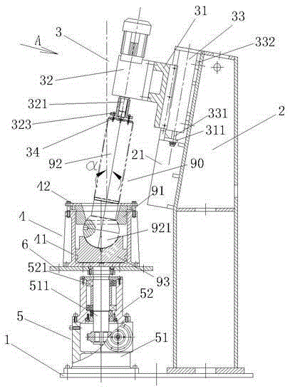
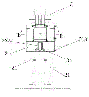
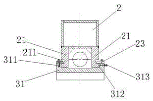
[0016] Such as Figure 1 ~ Figure 3 As shown, the present invention includes a bottom plate 1, a body 2, an upper center rotating device 3, a grinding tool 4, and a grinding tool rotating support device 5. The body 2 of this embodiment is a thick-walled hollow box type welded structure. The bottom of the upright body 2 is vertically fixed on the right end of the bottom plate 1, and the grinding tool rotating support device 5 is vertically fixed on the left end of the bottom plate 1. The upper center rotating device 3 is supported obliquely on the upper side of the fuselage 2 and includes a sliding seat 31, an upper motor-reducer combination 32, a sliding seat moving cylinder 33 and an upper center 34. The angle between the axis of the upper center 34 and the vertical is α =-9°~-11°, this embodiment is -10°, the included angle α simulates the working condition of the con...


PUM


Abstract

The invention discloses a grinder for a ball head assembly. The grinder comprises a bottom plate, a body, an abutting head rotating device, a grinding tool and a grinding tool rotating supporting device. The abutting head rotating device is arranged on one side of the upper portion of the body in a slant mode and comprises a sliding seat, an upper motor and reduction box set, a sliding seat moving oil cylinder and an abutting head. The inner sides of the sliding seat are arranged on two guide rails in a slant bridging manner, wherein the guide rails are arranged on the two sides of the upper portion of the body. One side of the upper motor and reduction box set is fixed to the outer side of the sliding seat. A reduction box output shaft is fixedly connected to the inner end of the abutting head. The front end of the sliding seat is connected with the end of a sliding seat moving oil cylinder piston rod. The grinding tool comprises a grinding seat and an upper cover, wherein the bottom of the grinding seat is fixed to the top end of the grinding tool rotating supporting device. According to the grinder, the grinding area among a ball head cover, a ball head and a ball bowl is enlarged, and therefore the contact area between the ball head cover, the ball head and the ball bowl is increased to more than 85% after grinding and painting check among the ball head cover, the ball head and the ball bowl, and ball head assembly grinding precision and efficiency are greatly improved.

Description

Technical field [0001] The invention relates to a special machine tool for grinding the transmission parts of a crank press, in particular to a special machine tool which can be used for grinding ball caps, ball heads and bowls at the same time, belonging to the technical field of special metal cutting machine tools. Background technique [0002] Such as figure 1 As shown, the ball head cover 91, the ball head rod 92 and the ball bowl 93 are called the ball head assembly 90. The ball head assembly is an important force transmission component of the crank press. The upper connecting rod of the ball head assembly is connected to the slider under the crank pressure. The power of the crankshaft of the machine is transmitted to the slider through the connecting rod and the ball head assembly to complete the stamping forming of the plate or the die forging forming of the heated blank. The upper end of the ball head rod is threadedly connected with the lower end of the connecting rod, ...

Claims


Application Information

Patent Timeline
IPC IPC(8): B24B15/08B24B41/06B24B47/12
CPCB24B15/08B24B41/06B24B47/12
Inventor 朱峰
Owner WORLD PRECISE MACHINERY CO LTD CHINA
Why Eureka
Try Eureka