Spectrograph

A spectrometer and spectrum technology, applied in the field of spectrometer, can solve problems such as the inability to effectively measure the degree or possibility of damage, and the inability to provide information on the optical radiation power density

Inactive Publication Date: 2016-01-27
UNITED POWER RES TECH CORP +1
View PDF3 Cites 1 Cited by
  • Summary
  • Abstract
  • Description
  • Claims
  • Application Information

AI Technical Summary

Problems solved by technology

[0004] Although the existing spectrometers can split the light to be measured to obtain the corresponding spectrum, the spectrum can only display the approximate composition of the various colors of the light to be measured, and cannot further analyze the blue light, ultraviolet light or other light that everyone is concerned about. The proportion of light in the wavelength band and its optical radiation power density provide information, so it is impossible to effectively measure the degree or possibility of damage to the human eye or various parts of the human body by the light emitted by the LED, or to evaluate the exposure to the eyes when using LED products. The intensity of blue light, ultraviolet light or light in other bands

Method used


Image

  • Spectrograph
  • Spectrograph
  • Spectrograph

Examples


no. 1 example

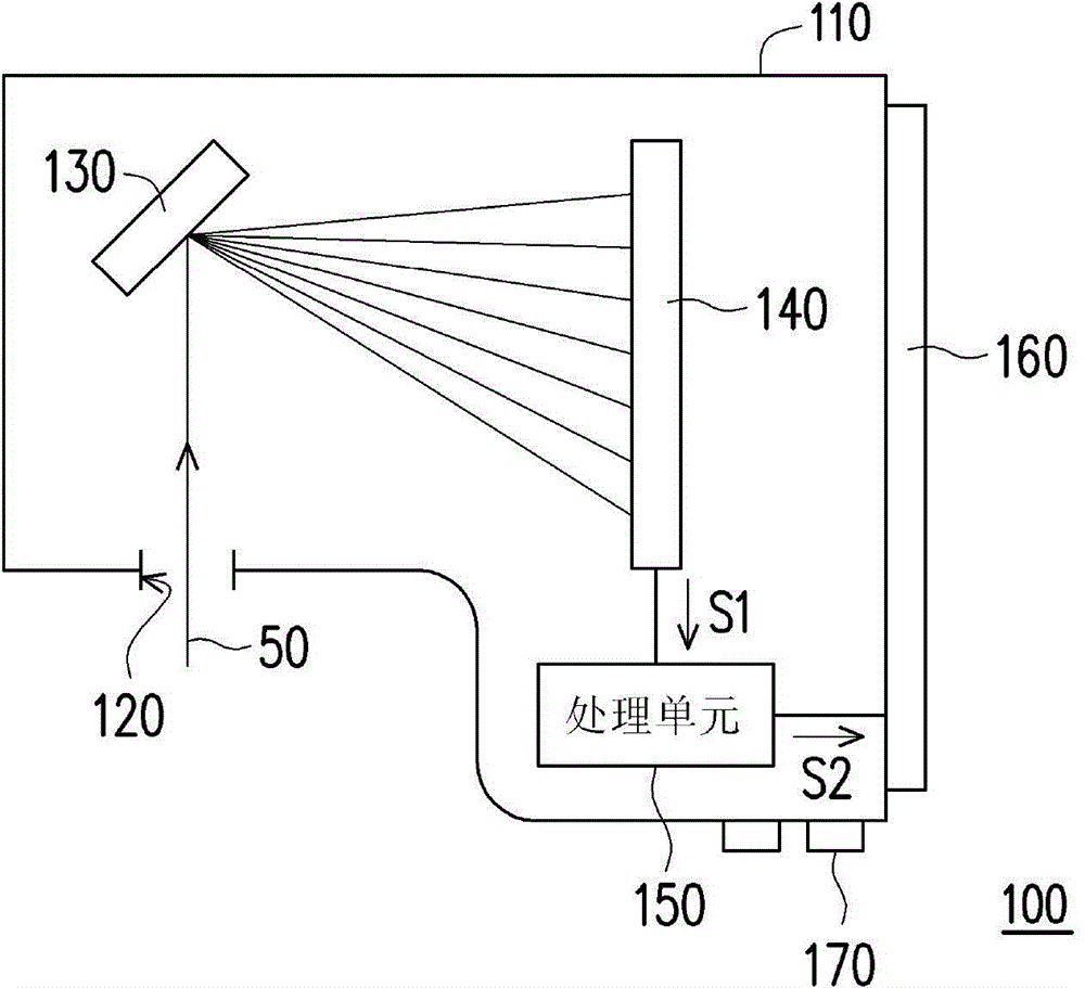
[0034] figure 1 It is a schematic diagram of the spectrometer of the first embodiment of the present invention. Please refer to figure 1 , the spectrometer 100 of this embodiment includes a spectroscopic unit 130 , a photodetector 140 and a processing unit 150 . In this embodiment, the spectrometer 100 may further include a casing 110 , and the spectroscopic unit 130 , the light detector 140 and the processing unit 150 are disposed in the casing 110 .

[0035] When using the spectrometer 100 of this embodiment to analyze the light to be measured 50, the light to be measured 50 can be incident into the spectrometer 100 from the light entrance hole 120 on the housing 110, and the different wavelength components of the light to be measured 50 can be separated by the spectroscopic unit 130 break down. In this embodiment, the light splitting unit 130 is, for example, a light splitting grating. However, in other embodiments, the light splitting unit 130 may also be a spectroscop...

no. 2 example

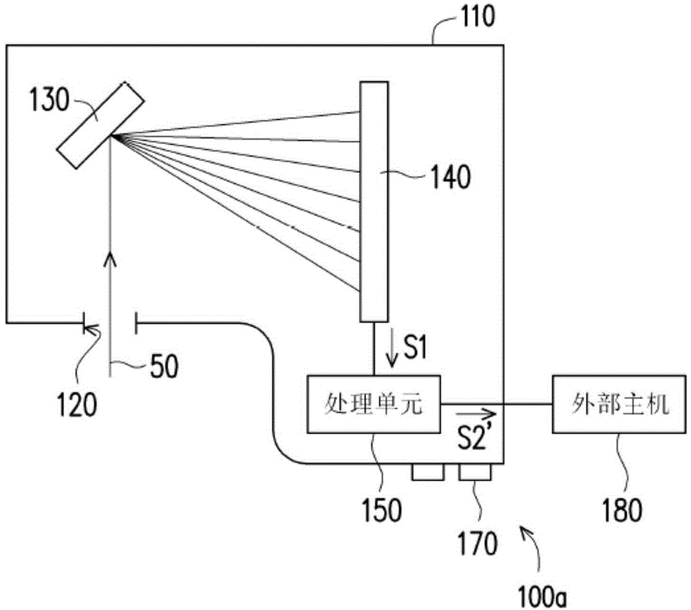
[0052] Although as mentioned above, the display unit 160 can be configured on the casing 110, the spectrometer 100 of the present invention can also not be provided with a display unit, but can output and display information through an external device, such as image 3 shown.

[0053] image 3 It is a schematic diagram of the spectrometer of the second embodiment of the present invention. Please refer to image 3 , the spectrometer 100a of this embodiment and figure 1 The spectrometer 100 is similar, while the differences between the two are described below. In this embodiment, the processing unit 150 can be electrically connected to the external host 180, and after the processing unit 150 calculates the ratio of the light radiation amount or the power density of the light radiation of the specific wave band of the light 50 to be measured, it will The ratio of the amount of light radiation or the power density of light radiation is transmitted to the external host 180 as a...


PUM


Abstract

The invention provides a spectrograph which is used for analyzing to-be-detected light. The spectrograph comprises a light splitting unit, a light detector, and a processing unit. The light splitting unit enables components with different wavelengths of the to-be-detected light to be decomposed. The light detector detects the decomposed to-be-detected light, so as obtain a spectrum. The processing unit is electrically connected to the light detector, and is used for calculating the proportion of light radiation quantity of the spectrum at a specified band to at least one of the total optical radiation power density, the total optical radiation power intensity and the total optical radiation quantity of the spectrum, wherein the specified band is within visible light from infrared light to ultraviolet light, and invisible light.

Description

technical field [0001] The invention relates to an optical measuring device, and in particular to a spectrometer. Background technique [0002] The eye is an important organ for human beings to perceive visual imaging, and is called the "window of the soul". With the wide application of light-emitting diode (Light Emitting Diode, referred to as LED) related products, discussing the impact of LED products on the eyes has gradually attracted the attention of the scientific and medical fields. After research by various parties, it was found that blue light and ultraviolet light, which are the main components of LED light sources, are one of the main causes of discomfort to the human eye or various parts of the human body. [0003] In the spectrum obtained by spectroscopically separating the white light LED light source, the energy in the wavelength range of blue light, ultraviolet light, etc. accounts for a large proportion. That is, staring at the LED light source for a long...

Claims


Application Information

Patent Timeline
Patent Type & Authority Applications(China)
IPC IPC(8): G01J3/457
Inventor 安振基林清隆沈峰旗
Owner UNITED POWER RES TECH CORP
Why Eureka
Try Eureka