
Geotechnical triaxial test sample radial deformation testing device and method

A technology of radial deformation and triaxial testing, which is applied in the direction of measuring devices, preparation of test samples, and application of stable tension/compression to test the strength of materials, etc., to achieve the effect of simple production, simple structure and low cost

Inactive Publication Date: 2016-01-27
CHINA UNIV OF MINING & TECH
View PDF8 Cites 8 Cited by
  • Summary
  • Abstract
  • Description
  • Claims
  • Application Information

AI Technical Summary

Problems solved by technology

However, this method must require that the pressure-tight chamber is transparent, which is acceptable for conventional geotechnical triaxial tests, but there are certain restrictions for high-pressure triaxial tests.

Method used


Image

  • Geotechnical triaxial test sample radial deformation testing device and method

Examples


Embodiment 1

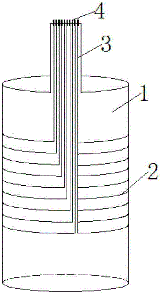
[0021] Assuming that the size of the triaxial test sample to be tested is a standard cylindrical sample of φ39.1mm×80mm, make a latex film 1 matching the cylindrical sample, and print an array of sensitive materials on the latex film 1 2 and the conductive electrode array 3, the printed sensitive material array 2 is set to 20 rows, the number of phases and rows of the conductive electrode array 3 connected to it is the same, and terminals 4 are connected to the ends of all the conductive electrode arrays 3. At the beginning of the test, first put the sample to be tested into the latex film 1 of the test device. When installing, ensure that the center position of the sensitive material array 2 coincides with the center position in the height direction of the sample. Install the sample into the test device, use the wire connection terminal 4 to connect the test device with the signal acquisition test instrument, apply pressure to the sample according to the geotechnical triaxial ...

Embodiment 2

[0024] Suppose the size of the triaxial test sample to be tested is a standard cylindrical sample of φ50mm×100mm, and the sensitive material array 2 and the conductive electrode array 3 are printed on the supporting latex film 1 respectively, and the sensitive material array 2 has 30 rows The conductive electrode array 3 connected to the sensitive material array 2 is also 30 rows, and the terminal 4 is connected to the end of the conductive electrode array 3 in the 30 rows. At the beginning of the test, first put the sample to be tested into the latex film 1 of the test device. When installing, ensure that the center position of the sensitive material array 2 coincides with the center position in the height direction of the sample, and then insert the test sample according to the conventional test method. A cylindrical sample of the device is installed in the test apparatus. Connect the test device with the external test instrument by using the wire connecting terminal 4 . Tu...


PUM


Abstract

The invention discloses a geotechnical triaxial test sample radial deformation testing device and method. The device is composed of a latex film, a sensitive material array printed on the latex film, a conductive electrode array printed on the latex film and a terminal connected with the conductive electrode array. The latex film is normally adopted in a triaxial test and wraps a sample during testing. The sensitive material array printed on the latex film must be the rubber-based sensitive composite material. On the one hand, large deformation is ensured, and on the other hand, it is ensured that the sensitive material array is firmly stuck to the latex film. The conductive electrode array printed on the latex film must be the rubber-based conductive composite material, so that it is ensured that the large-deformation feature is achieved and the conductive electrode array is firmly connected with the latex film. The terminal connected with the conductive electrode array is used for connecting the device with a testing instrument. During testing, the radial deformation distribution of the sample in the height direction can be worked out only by testing all resistances of the sensitive material array. The method can meet the requirement of high pressure and conventional triaxial testing and has the practical value.

Description

technical field [0001] The invention relates to a testing device and method, especially a geotechnical triaxial test sample suitable for deformation testing [0002] Radial deformation testing device and method. Background technique [0003] Triaxial test is an important test of soil mechanics. It puts a cylindrical soil sample in a closed pressure chamber, and simulates the stress of the actual soil layer by applying uniform surrounding pressure and axial deviation stress in all directions. Based on this, the strength and stress-strain constitutive relationship of soil are studied. The main steps are as follows: cover the latex film on the cylinder made of soil or directly fill the sample with soil in the latex film and place it in a sealed pressure chamber. The lower end of the latex membrane is bound to the base, and the upper end is bound to the sample cap, so that the pore water in the sample is completely separated from the water in the pressure chamber. The pore wa...

Claims


Application Information

Patent Timeline
Patent Type & Authority Applications(China)
IPC IPC(8): G01N3/08G01N1/28G01N3/06
Inventor 周国庆廖波季雨坤周檀君赵光思梁恒昌赵晓东况联飞王建州
Owner CHINA UNIV OF MINING & TECH
Learn More