Detection circuit

A detection circuit and circuit technology, applied in the direction of measuring electricity, measuring electrical variables, measuring devices, etc., can solve the problem of low accuracy of detection results and achieve the effect of improving accuracy

Inactive Publication Date: 2016-01-27
EMERSON NETWORK POWER CO LTD
View PDF7 Cites 8 Cited by
  • Summary
  • Abstract
  • Description
  • Claims
  • Application Information

AI Technical Summary

Problems solved by technology

[0007] In view of this, the embodiment of the present invention provides a detection circuit to solve the problem in the prior art that an auxiliary contact needs to be used and the resulting detection result is not accurate

Method used


Image

  • Detection circuit
  • Detection circuit
  • Detection circuit

Examples


Embodiment 1

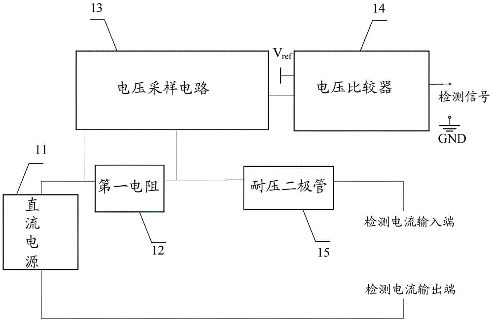
[0059] Embodiment 1 of the present invention provides a detection circuit for detecting the on-off between two points in the DC circuit, and its structural diagram is as follows figure 2 As shown, the detection circuit includes: a DC power supply 11, a first resistor 12, a voltage sampling circuit 13 and a voltage comparator 14, wherein:

[0060] A DC power supply 11, the anode of which is connected to the first end of the first resistor, and the cathode of which is connected to the detection current output end, for generating a detection current;

[0061] The first resistor 12, the second terminal of which is connected to the detection current input terminal, is used to limit the current in the detection circuit; the current in the detection circuit is limited below a set value, and the set value can be determined according to empirical values.

[0062] The first resistor is the resistor used to limit the current. Because of its large resistance value, the detection current ...

Embodiment 2

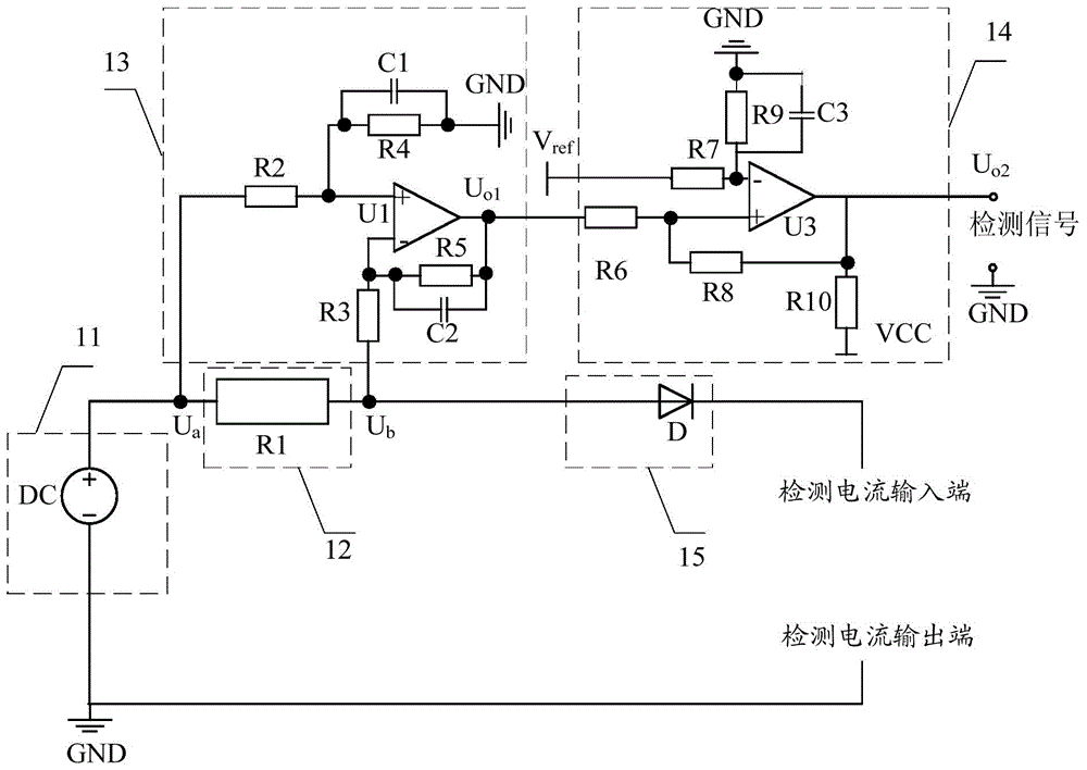
[0070] In Embodiment 2 of the present invention, when the voltage sampling circuit 13 samples the voltage at both ends of the first resistor, it includes a differential amplifier circuit; when the voltage sampling circuit 13 samples the potential at the second end of the first resistor , including a positive-phase proportional amplification circuit or an inverse-phase proportional amplification circuit.

[0071] Commonly used voltage comparators include zero-crossing voltage comparators, zero-crossing comparators with hysteresis characteristics, hysteresis voltage comparators, and double-limit voltage comparators. Any one of the above-mentioned voltage comparators can be used to realize the present invention. function of the voltage comparator. Considering that the hysteresis voltage comparator can realize the hysteresis characteristic of the comparison signal and improve the reliability and accuracy of the detection circuit, therefore, in the second example of the present inv...


PUM


Abstract

The invention provides a detection circuit which is used to detect connection state between two points in a DC circuit. The detection circuit comprises a DC power supply, a first resistor for limiting current, a voltage sampling circuit and a voltage comparator, wherein the voltage sampling circuit outputs the voltage between the two ends of the first resistor or a sampling result of one end, far from the anode of the DC power supply, of the first resistor to the positive-phase input end of the voltage comparator; and the voltage comparator compares the result with a reference voltage that is input to the negative-phase end of the comparator, and outputs a corresponding signals to indicate a connection or disconnection state between the two ends of a tested device. The connection state between two points in the DC circuit can be detected, the current limiting first resistor has functions of an isolated DC circuit and a detection circuit, mechanical devices as an auxiliary contact are not needed, false detection caused by the device is low in motion speed and easy to corrode is avoided, and the accuracy of the detection result is improved.

Description

technical field [0001] The invention relates to power electronics technology, in particular to a detection circuit. Background technique [0002] With the rapid development of modern power electronics technology towards high power and high voltage levels, fault detection technology is becoming more and more important. The two-point on-off detection technology in the DC circuit is an important fault detection technology. The relevant fault detection in the DC circuit includes two-port devices such as contactors, fuses, and switch tubes, as well as the detection of continuity between the two ports of the cable. [0003] When there is a high DC voltage between two points in the circuit, the electrical isolation between the detection circuit and the main circuit (the DC circuit where the device under test is located) needs to be considered. The device under test in the main circuit has no auxiliary contacts. In order to isolate the detection circuit from the main circuit, it i...

Claims


Application Information

Patent Timeline
Patent Type & Authority Applications(China)
IPC IPC(8): G01R31/02
Inventor 刘青移李伟铭蔡子海陈坤鹏罗劼曾显达马彦锋
Owner EMERSON NETWORK POWER CO LTD
Why Eureka
Try Eureka