Integrated high-return-loss optical component adapter

An adapter and high return loss technology, applied in optical components, light guides, optics, etc., can solve the problems of affecting the quality of transmission signals, reducing the signal-to-noise ratio of communication, and increasing processing costs, so as to improve optical performance and optical return loss , the general effect of the interface

Inactive Publication Date: 2016-01-27
黄石晨信光电股份有限公司
View PDF6 Cites 6 Cited by
  • Summary
  • Abstract
  • Description
  • Claims
  • Application Information

AI Technical Summary

Problems solved by technology

[0003] In recent years, with the rapid development of optical communication, the optical communication network is developing in the direction of large capacity and long distance. Therefore, the requirements for signal coupling input and output of optical communication modules are getting higher and higher. In comparison, current components The adapter has limitations under this requirement, which are mainly reflected in: (1) Since the component adapter and the fiber optic connector are connected by PC (ordinary spherical surface), and the end face of the ceramic ferrule has not been specially treated, the return caused by the end face connection The increase of the optical power directly affects the quality of the transmitted signal, thereby reducing the communication signal-to-noise ratio; (2) The current component adapter cannot be directly connected to the optical fiber connector when it is assembled on the module because it does not have a standard connector port. For docking, the corresponding plug-in adapter parts must be assembled to form a common interface, and then docked with the optical fiber connector, so that not only the installation process is cumbersome, time-consuming and laborious, but also increases the corresponding processing cost

Method used


Image

  • Integrated high-return-loss optical component adapter
  • Integrated high-return-loss optical component adapter
  • Integrated high-return-loss optical component adapter

Examples


Embodiment Construction

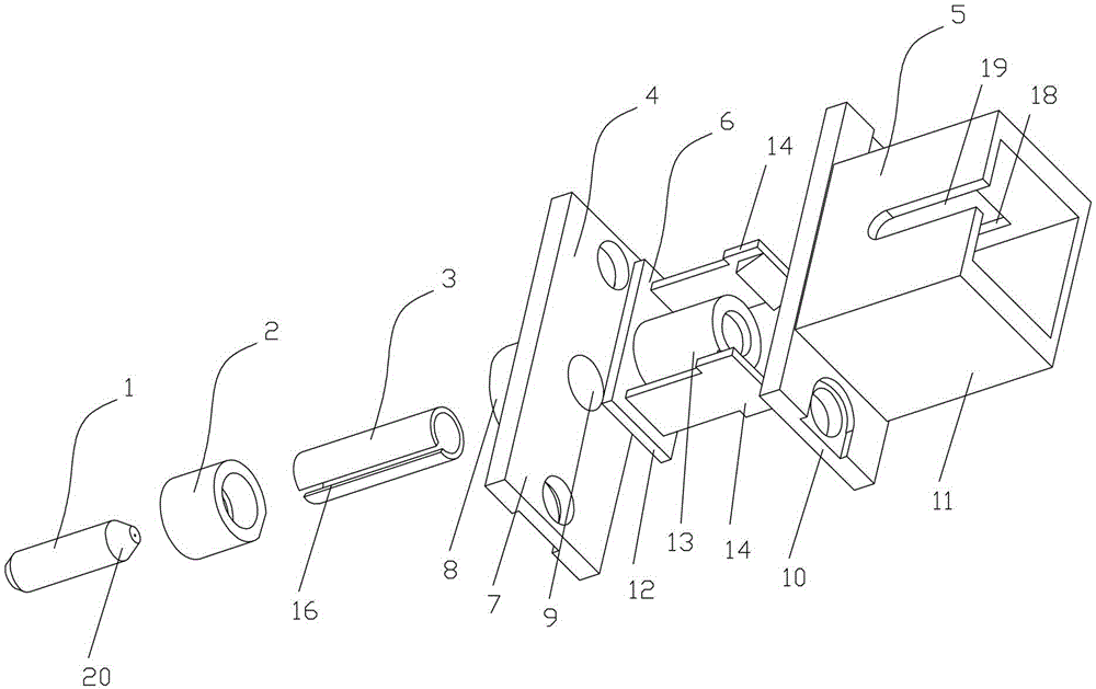
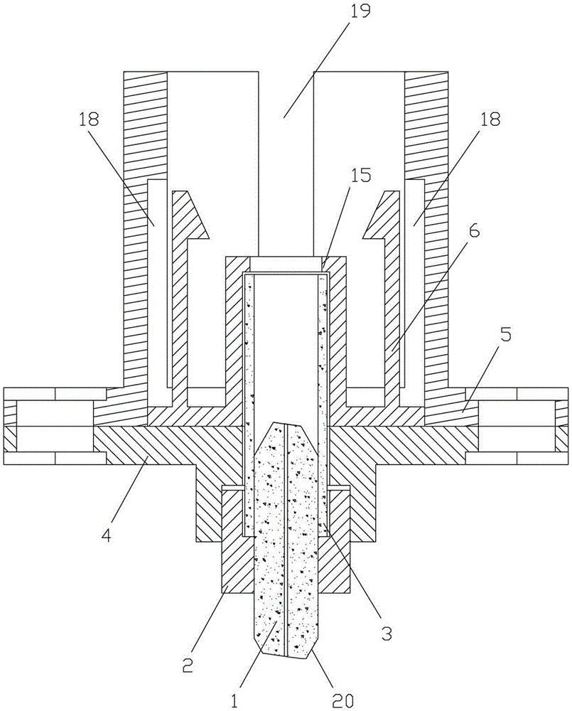
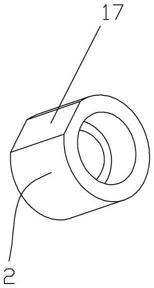
[0018] see Figure 1-3 , the present invention includes plug-in adapter parts, ceramic ferrule 1, positioning metal ring 2 and ceramic sleeve 3, plug-in adapter parts include front and rear seats 4, 5 and card holder 6, and front seat 4 has The bottom plate A7 and the protruding structure 8 arranged on the end surface of the bottom plate A7 and the stepped through hole 9 passing through the bottom plate A7 and the protruding structure 8, and the aperture of the through hole on the protruding structure 8 is larger than the aperture of the through hole on the bottom plate A7 , the rear seat 5 has a bottom plate B10, and a cylindrical shell 11 is arranged on the end surface of the bottom plate B10, wherein the bottom plate A7 matches the bottom plate B10 and is fastened and connected by bolts; 5 Pressed on the bottom plate A7 (there is a groove on the end surface of the bottom plate B10 that fits the bottom plate A7, and the groove matches the bottom plate C12), and a limit sleev...


PUM


Abstract

An integrated high-return-loss optical component adapter comprises a plug type adapter part, a ceramic plug core, a positioning metal ring and a ceramic sleeve. The plug type adapter part comprises a front base, a rear base and a clamping base. The front base is provided with a bottom plate A, a protruding structure and a step-shaped through hole penetrating the bottom plate A and the protruding structure. The rear base is provided with a bottom plate B and a cylindrical shell, and the bottom plate A and the bottom plate B are connected in a matched mode. The clamping base is provided with a bottom plate C, a limiting sleeve and an elastic clamping plate, and the bottom plate C is pressed to the bottom plate A through the rear base. The positioning metal ring is arranged in the portion, in the protruding structure, of the through hole in a sleeved mode. The two ends of the ceramic sleeve are inserted in the portion, in the bottom plate A, of the through hole and the limiting sleeve respectively. The ceramic plug core and the positioning metal ring are in interference fit, and one end of the ceramic plug core is inserted in the ceramic sleeve. By means of the integrated high-return-loss optical component adapter, the ceramic plug core, the ceramic sleeve and the plug type adapter part can be integrally and coaxially assembled, the structure is compact, a connector is universal, installation and use are convenient, optical performance is good, and the integrated high-return-loss optical component adapter is widely applied to the fields of optical communication modules and photoelectric detectors.

Description

technical field [0001] The invention relates to an optical fiber adapter, in particular to an integrated high return loss optical component adapter. Background technique [0002] At present, the component adapter is a passive device that is precisely assembled by a ceramic ferrule, a guide sleeve and an external metal tube body. hole, and pre-embed the optical fiber in the inner hole, and achieve low insertion loss, high return loss and other performances by grinding and polishing the end face of the ceramic ferrule. Component adapters are widely used in the coupling input and output of optical signals of optical transceiver modules and the coupling input and output of optical signals of optical detectors. [0003] In recent years, with the rapid development of optical communication, the optical communication network is developing in the direction of large capacity and long distance. Therefore, the requirements for signal coupling input and output of optical communication m...

Claims


Application Information

Patent Timeline
Patent Type & Authority Applications(China)
IPC IPC(8): G02B6/38
CPCG02B6/3825
Inventor 叶苍竹吴远策官守军戴正华万晶
Owner 黄石晨信光电股份有限公司
Why Eureka
Try Eureka