
Display roughness detection method and detection system of display

A detection method and detection system technology, applied in the direction of static indicators, instruments, etc., can solve problems such as distortion, rough image, display imaging difference, etc., and achieve the effects of small impact, convenient installation and maintenance, and strong heat dissipation

Active Publication Date: 2018-04-20
SHANGHAI VISTEON AUTOMOTIVE ELECTRONICS SYST
View PDF5 Cites 0 Cited by
  • Summary
  • Abstract
  • Description
  • Claims
  • Application Information

AI Technical Summary

Problems solved by technology

[0006] 3. It is precisely because of the difference in imaging mechanism and principle that the imaging difference between the two displays is caused
[0007] After in-depth research, it is found that after the original image is subjected to optical processing such as magnification and reflection, the shape of the original pixel is distorted, and the image becomes rough

Method used


Image

  • Display roughness detection method and detection system of display
  • Display roughness detection method and detection system of display
  • Display roughness detection method and detection system of display

Examples


Embodiment Construction

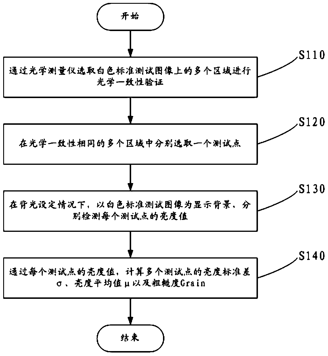
[0035] Such as figure 1 As shown, a display roughness detection method of a display, the method comprising:

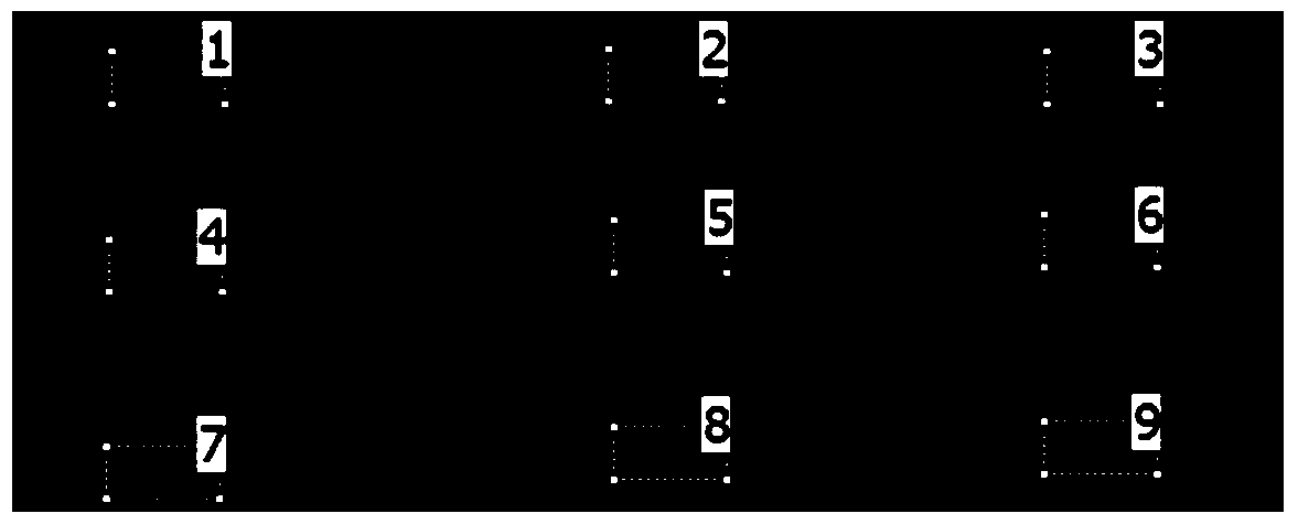
[0036] S110. Select a plurality of areas on the white standard test image by an optical measuring instrument to perform optical consistency verification. If the optical consistency difference of the plurality of areas is greater than or equal to a threshold value, select a plurality of areas on the white standard test image again until the The optical identity of multiple regions is the same, that is, the difference in optical identity is less than a threshold value, which is 4.5%-5.5%;

[0037] Among them, the optical measuring instrument is an optical measuring instrument from Technoteam in Germany.

[0038] Roughness refers to the distortion of the pixel shape of the original image after optical processing such as magnification and reflection, which leads to the roughness of the image visually. The optical consistency reflects the effect of the backlight of the di...


PUM


Abstract

A method for detecting display roughness of a display, comprising: selecting a plurality of areas on a white standard test image by an optical measuring instrument for optical consistency verification, and if the difference in optical consistency of the plurality of areas is greater than or equal to a threshold value, re-inspecting the Select a plurality of regions on the white standard test image until the optical consistency of the plurality of regions is the same, that is, the difference in optical consistency is less than the threshold; respectively select a test point in a plurality of regions with the same optical consistency; Under the backlight setting situation, with the white standard test image as the display background, detect the brightness value of each of the test points respectively; through the brightness value of each of the test points, calculate the brightness standard deviation σ of a plurality of test points And the average value of brightness μ, the roughness Grain is calculated by the following formula: the present invention can detect the roughness conveniently, effectively and quickly, with low cost and high reliability, and can be used to measure the quality of the display effect of the projection display.

Description

technical field [0001] The invention belongs to the technical field of display effect measurement of a display, and in particular relates to a display roughness detection method of a display and a detection system thereof. Background technique [0002] Usually we evaluate the display effect of the display by the visual range of the screen, resolution, pixel pitch, brightness, color, refresh rate, etc. These measurement indicators can comprehensively and objectively judge the characteristics of ordinary liquid crystal display, CRT and rear projection display products. [0003] However, when developing a new projection display, it was found that the previous measurement items could not objectively evaluate the display effect of the projection display: [0004] 1. The projection display reflects the image to the human eye through two reflections. Unlike the real image directly produced on the original display, the image of the projection display seen by the human eye is actua...

Claims


Application Information

Patent Timeline
Patent Type & Authority Patents(China)
IPC IPC(8): G09G3/00
Inventor 朱珉辉
Owner SHANGHAI VISTEON AUTOMOTIVE ELECTRONICS SYST
Learn More