Piezoelectric driven rapid cooling device

A heat dissipation device and piezoelectric drive technology, applied in the direction of cooling/ventilation/heating transformation, etc., can solve the problems of unfavorable protection of electronic chips, discount of heat dissipation, etc., and achieve the effects of accelerated flow speed, controllable vibration speed, and accelerated heat dissipation

Inactive Publication Date: 2016-01-27
NANJING UNIV OF AERONAUTICS & ASTRONAUTICS
View PDF4 Cites 4 Cited by
  • Summary
  • Abstract
  • Description
  • Claims
  • Application Information

AI Technical Summary

Problems solved by technology

Regardless of the shape of the fins of the heat sink, once the heat sink is installed in a narrow space, the heat dissipation effect of

Method used


Image

  • Piezoelectric driven rapid cooling device
  • Piezoelectric driven rapid cooling device

Examples


Example Embodiment

[0020] The technical scheme of the present invention will be further described in detail below in conjunction with the accompanying drawings:

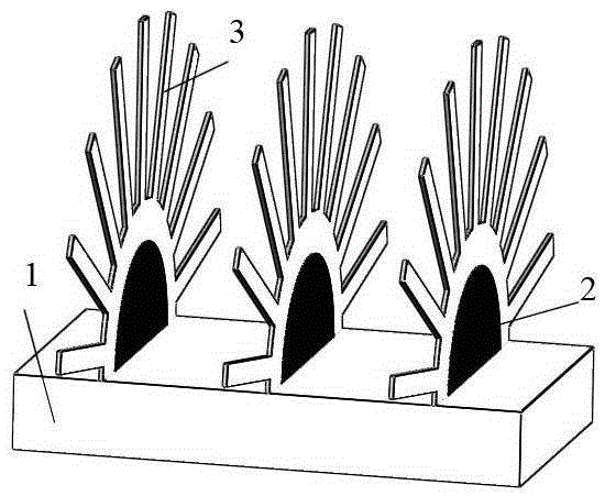
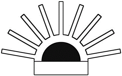
[0021] Such as figure 1 with figure 2 As shown, the present invention discloses a piezoelectric-driven rapid heat dissipation device, which includes a base and a number of flexible heat sinks arranged on the base;

[0022] Both the base and the flexible heat sink are made of thermally conductive materials;

[0023] The flexible heat sink is in the shape of a thin sheet and is prone to vibration and bending, and includes a vibration unit and a plurality of strip heat dissipation units arranged on the vibration part;

[0024] The vibration unit is fixed on the base, and the surface is provided with a piezoelectric layer made of piezoelectric material;

[0025] The piezoelectric layer is insulated from the vibrating unit, and is used to drive the vibrating unit to vibrate when alternating current is connected to both sides of the piezoelectric la...


PUM


Abstract

The invention discloses a piezoelectric driven rapid cooling device which comprises a base and a plurality of flexible cooling fins, wherein the plurality of flexible cooling fins are arranged on the base, the base and the flexible cooling fins are made of heat conduction materials, the flexible cooling fins are sheet-shaped and are easy to generate vibration and be bent, each flexible cooling fin comprises a vibration unit and a plurality of strip cooling units, the plurality of strip cooling units are arranged on a vibration part, the vibration unit is fixed on the base, a piezoelectric layer is arranged on the surface of the vibration unit and made of piezoelectric material, the piezoelectric layer and the vibration unit are isolated, and the piezoelectric layer is used for driving the vibration unit to vibrate during alternating current accessed to the two surfaces of the piezoelectric layer. The piezoelectric driven rapid cooling device has a controllable flexible fin vibration speed, and the cooling effect of an electronic chip in a narrow space with relatively low air velocity can be accelerated.

Description

Technical field [0001] The invention relates to the field of heat dissipation of electronic chips, in particular to a fast heat dissipation device driven by piezoelectricity. Background technique [0002] At present, the well-known method for cooling electronic chips in the industrial heat dissipation field is generally to directly connect the heat sink and the electronic chip together, and promote the cooling of the electronic chip through the heat dissipation effect of the heat sink, and control the temperature of the electronic chip not to exceed the upper limit temperature. In order to achieve protection. In the industry, heat sinks refer to miniature heat sinks. Most of these heat sinks are made of metals or alloys with high thermal conductivity such as aluminum alloy and copper. [0003] Then the most common heat sinks in the industrial heat dissipation field are all fixed structures. Regardless of the shape of the fins of the heat sink, once the heat sink is installed in a...

Claims


Application Information

Patent Timeline
IPC IPC(8): H05K7/20
Inventor 李鑫郡李国华
Owner NANJING UNIV OF AERONAUTICS & ASTRONAUTICS
Why Eureka
Try Eureka