Hot stamping machine

A technology of hot embossing equipment and embossing equipment, which is used in printing, printing presses, transfer printing and other directions, and can solve problems such as uncleanness in the embossing process

Active Publication Date: 2016-01-27
LEONHARD KURZ STIFTUNG & CO KG
View PDF8 Cites 4 Cited by
  • Summary
  • Abstract
  • Description
  • Claims
  • Application Information

AI Technical Summary

Problems solved by technology

If the carrier film is detached too early, this leads to uncleanness during the embossing process, especially in the case of fine and very fine structures

Method used


Image

  • Hot stamping machine
  • Hot stamping machine
  • Hot stamping machine

Examples


Embodiment Construction

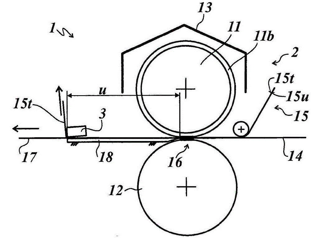
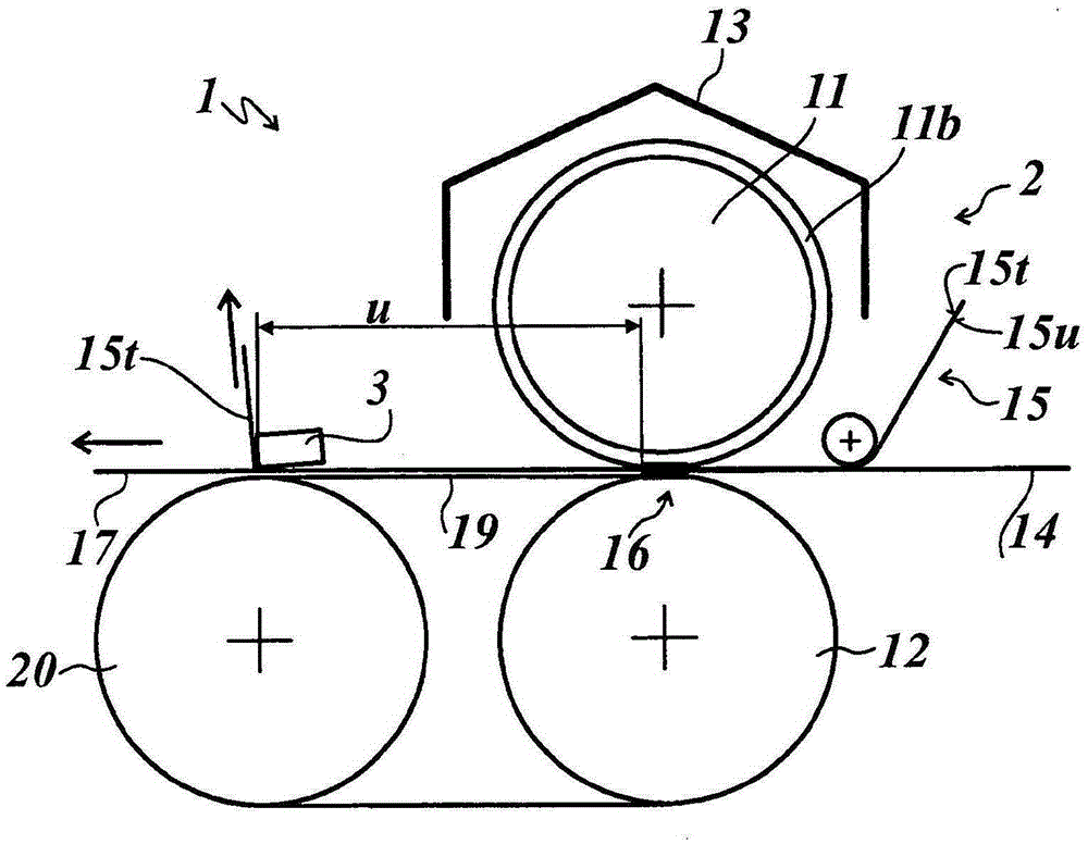
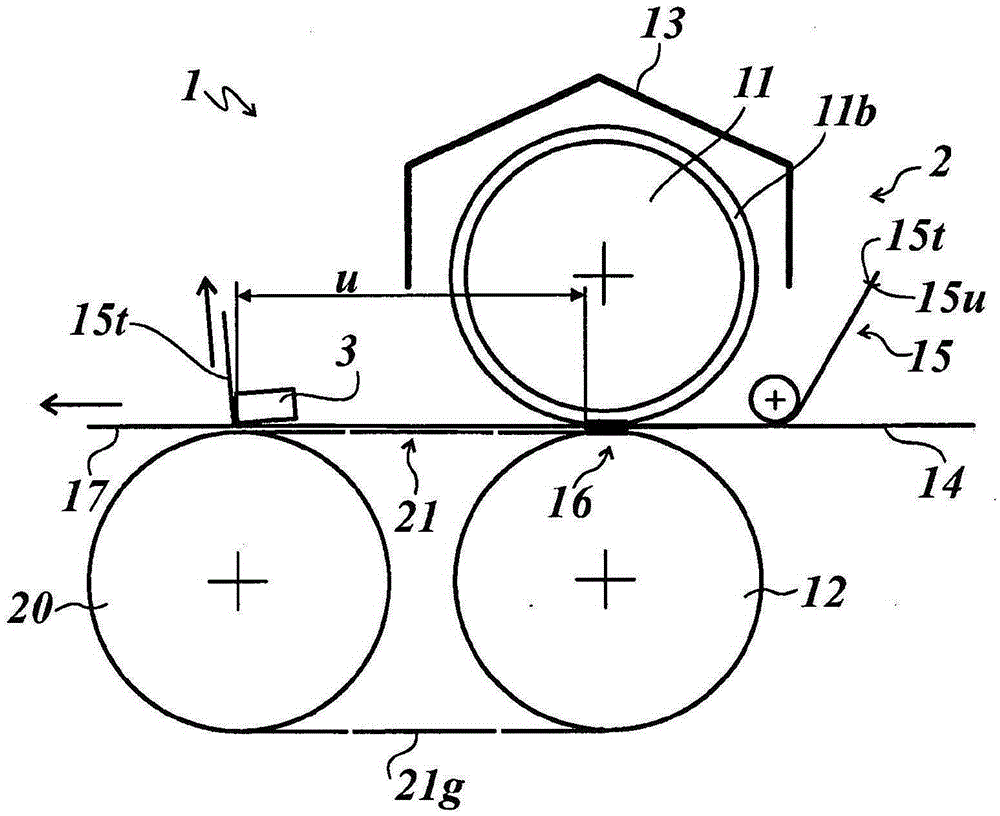
[0031] figure 1 A thermal embossing device 1 is shown, which has an embossing device 2 and a stripping device 3 . The embossing apparatus 2 includes an embossing roller 11 , a counter-pressing roller 12 and a heating device 13 .

[0032] The embossing roller 11 has, on its outer circumference, a coating 11 b made of an elastomer having a thickness in the range of 3 to 10 mm, preferably in the range of 5 to 10 mm. The elastomer is preferably silicone rubber. exist figure 1 In the example shown, the silicone rubber has a hardness of 80° Shore A. The counter pressure roller 12 is made of steel.

[0033] The heating device 13 is arranged above the embossing roller 11 and figure 1 The embodiment shown in is configured as an infrared radiation heating device controlled by means of a temperature controller.

[0034]Upstream of the embossing device 2, the substrate 14 to be embossed and the hot embossing film 15 are fed in, forming an embossing pressure in the embossing gap 16 f...


PUM


Abstract

The invention relates to a hot stamping machine (1), comprising a stamping device (2) for transferring a transfer layer (15u) arranged on a carrier layer (15t) of a hot stamping foil (15) onto a substrate (14). The hot stamping machine comprises a heatable stamping roller (11) and a counter-pressure roller (12) between which is stamping gap (16) is defined, and a downstream releasing device (3) for releasing the carrier layer (15t) from the transfer layer (15u) transferred onto the substrate (14). Between the stamping gap (16) and the releasing device (3) a flat contact element (18) is arranged below the stamped substrate (17), which contact element is directly contiguous to the stamping gap (16) or is spaced apart from the stamping gap (16) by less than 1mm or is arranged to overlap the stamping gap (16).

Description

technical field [0001] The invention relates to a thermal embossing device according to the preamble of the content of claim 1 . [0002] Thermal embossing equipment is used to transfer the transfer layer provided on the carrier layer of the thermal embossing film to the substrate under the action of temperature and pressure. For this purpose, a heated embossing roller is provided, which interacts with a counter-pressure roller. Downstream of the embossing nip formed between embossing roller and counter roller, the carrier layer is detached from the transfer layer which has been transferred to the substrate by means of a stripping device. When using an embossing roller with a relief profile, only those regions of the transfer layer which correspond in particular to the shape of the relief of the embossing roller are transferred onto the substrate, so that the detached carrier layer also has the particular characteristics of the transfer layer. It is the remaining part corres...

Claims


Application Information

Patent Timeline
Patent Type & Authority Applications(China)
IPC IPC(8): B44B5/00B44B5/02B44C1/17B41F19/06
CPCB41F16/0026B41F16/0093B44B5/0047B44B5/028B44C1/1729B44C1/17
Inventor M·特里佩尔R·比伯
Owner LEONHARD KURZ STIFTUNG & CO KG
Why Eureka
Try Eureka