
A Ring Swirl Plate Separator

A swirl plate and separator technology, which is applied in the field of ring-enclosed swirl plate separators, can solve the problems of reduced operating pressure drop and low separation efficiency of small particle size particles, and achieves reduced pressure drop, simple structure, and low difficulty in construction. big effect

Active Publication Date: 2017-05-10
HUNAN UNIV
View PDF6 Cites 0 Cited by
  • Summary
  • Abstract
  • Description
  • Claims
  • Application Information

AI Technical Summary

Problems solved by technology

[0006] The present invention aims to provide a ring-encircled swirl plate separator, which has a simple structure, can completely solve the problem of low separation efficiency of small particle size particles in principle, can reduce the operating pressure drop, and can be flexibly adjusted according to requirements. Design and upgrading, easy to promote

Method used


Image

  • A Ring Swirl Plate Separator
  • A Ring Swirl Plate Separator
  • A Ring Swirl Plate Separator

Examples


Embodiment Construction

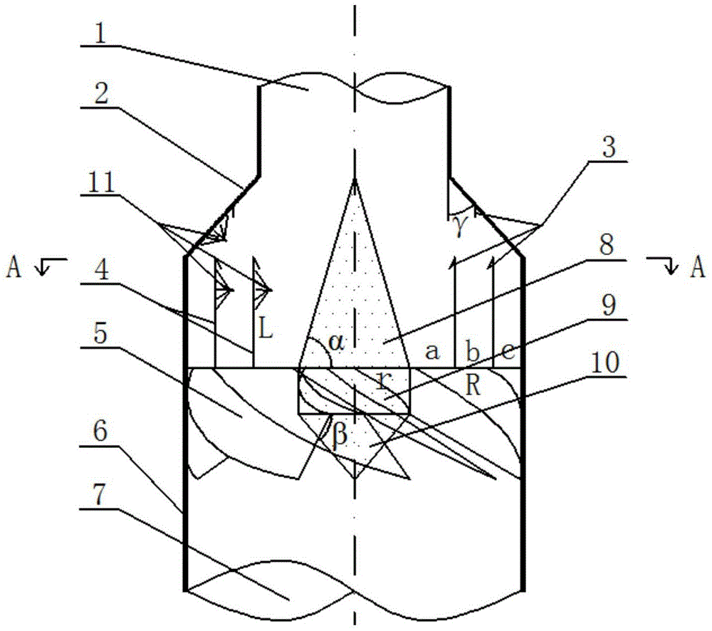
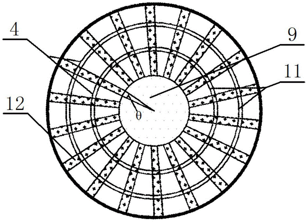
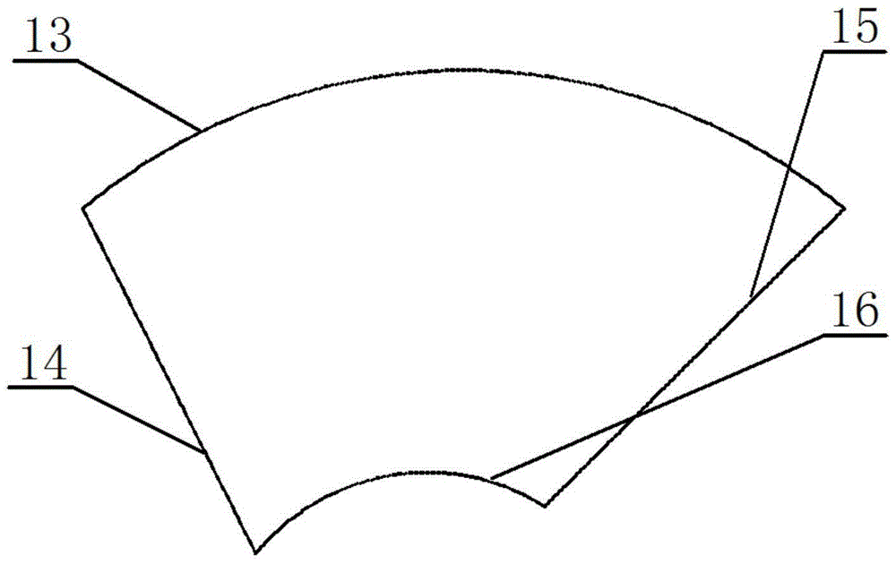
[0039] A ring-encircled swirl plate separator, such as figure 1As shown, a ring-added swirl plate separation device includes a swirl plate 5, a separation ring 4 fixed on the swirl plate 5, a contraction wall 2, an annular cover 11 on the separation ring 4 and the contraction wall 2, and a flushing nozzle 3 , the lower cone 10, the middle cylinder 9 and the upper cone 8. The swirl plate 5 is composed of a plurality of swirl plate blades, which are welded and fixed between the middle cylinder 9 and the outer wall 6. The inclination angle of the swirl plate blades is designed to be between 45°-60°, and the width of the blade overlapping area 12 is consistent inside and outside. , the θ angle is about 5°-15°, and its upper boundary 14 can be horizontal or inclined, but the points with the same radius on all blades are all on the same height, which is convenient for welding and fixing the separation ring 4, the lower boundary of the swirl plate 5 15 is inclined, so as to guide th...


PUM

PropertyMeasurementUnit
lengthaaaaaaaaaa

Abstract

The invention discloses a ring whirlwind plate separator. The ring whirlwind plate separator comprises a cylindrical outer wall of which the top end is provided with an outlet, an inner solid body vertically arranged in the outer wall, a whirlwind plate fixedly connected between the outer wall and the inner solid body, and a separation ring. The inner solid body is used for promoting air to flow close to the outer wall surface and accelerating a fluid flowing rate. The whirlwind plate is used for blocking particles and promoting air flow rotation. The separation ring is used for shortening a particle centrifugation motion distance. The separation ring is circularly fixed to the whirlwind plate. The ring whirlwind plate separator reduces critical separation particle sizes and can be designed in a low pressure drop scope.

Description

technical field [0001] The invention relates to a ring-enclosed swirl plate separator, which belongs to the technical field of material separation, and is especially suitable for gas-liquid separation in flue gas wet purification projects, and in particular relates to the design principle of a ring-enclosed swirl plate separator structure The theoretical calculation process and the characteristics of the material separation in the quantitative design. Background technique [0002] The swirl plate separator uses swirl blades to make the gas rotate, and under the action of centrifugal force, it achieves the purpose of separating gas-liquid and gas-solid. Due to its simple structure and good separation efficiency, it is widely used in chemical industry, mining and metallurgy, food, medicine, electric power and environmental protection and other industries, such as gas-liquid separation in the chemical production process of acrylonitrile and melamine, etc. Demisting during air-...

Claims


Application Information

Patent Timeline
Patent Type & Authority Patents(China)
IPC IPC(8): B01D45/14
Inventor 李彩亭肖育军李珊红
Owner HUNAN UNIV
Learn More