Low-temperature denitration device and method for denitration through low-temperature denitration device

A low-temperature denitrification and denitrification technology, applied in separation methods, chemical instruments and methods, and dispersed particle separation, can solve problems such as catalyst deactivation, increase reaction contact surface and probability, improve denitrification efficiency, and improve low-temperature denitrification capabilities. Effect

Active Publication Date: 2016-02-03
江苏海澜正和环境科技有限公司
View PDF3 Cites 2 Cited by
  • Summary
  • Abstract
  • Description
  • Claims
  • Application Information

AI Technical Summary

Problems solved by technology

[0004] At present, a relatively advanced gas denitrification method is selective catalytic reduction denitrification technology (SCR). The exhaust gas containing nitrogen oxides is mixed with ammonia gas in a certain proportion and sent to the SCR reactor. The role of the catalyst in the SCR reactor makes nitrogen oxides react with ammonia to generate ammonia and water to achieve the purpose of gas denitrification, but the existing denitrification reaction device is mainly designed for medium and high temperature catalyst denitrification, and its operating temperature is 300 ℃~420℃ or even higher, and the flue gas emitted from the tail of almost all combustion devices in these industries is less than 220℃. In the production of ammonium sulfate and ammonium bisulfate, ammonium sulfate and ammonium bisulfate will cover the micropores of the catalyst in the denitrification reaction device, resulting in rapid deactivation of the catalyst. Therefore, the research and development of denitrification technology in the low temperature section will open up a huge environmental protection market

Method used


Image

  • Low-temperature denitration device and method for denitration through low-temperature denitration device
  • Low-temperature denitration device and method for denitration through low-temperature denitration device

Examples


Embodiment 1

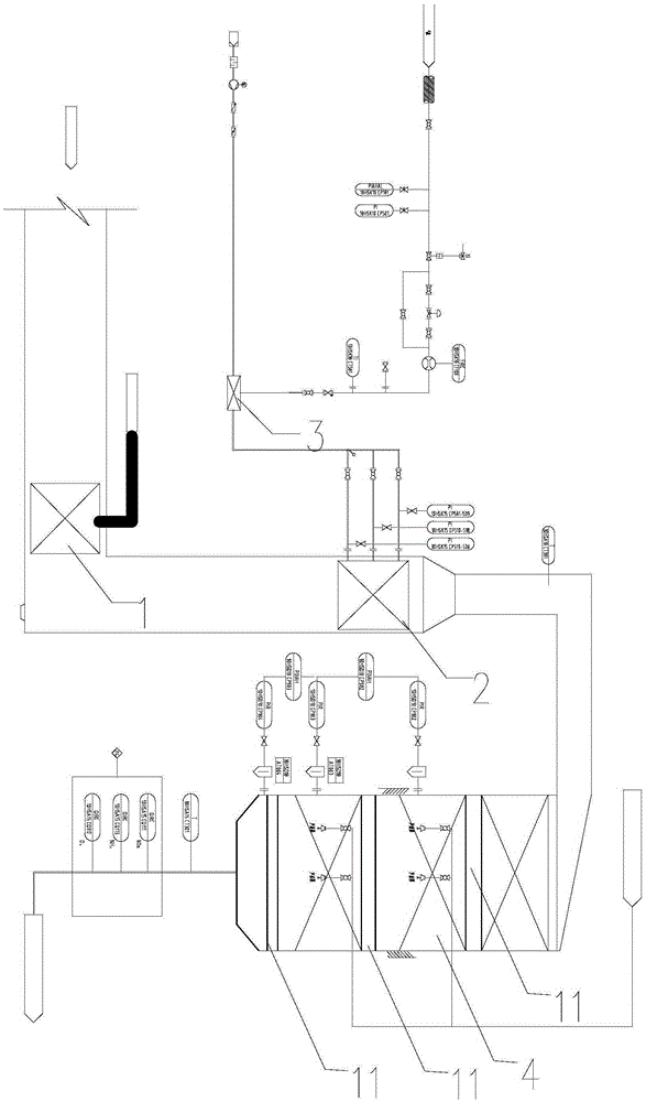
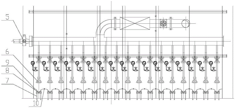
[0023] Embodiment 1: A kind of low temperature denitrification device, its structure is as follows figure 1 As shown, it includes an ammonia adding device 2, a mixing device 3 and a reaction device 4, the ammonia adding device 2 is embedded and connected in the flue, the mixing device 3 and the reaction device 4 are placed outside the flue, and the ammonia adding device The outlet of 2 communicates with the inlet of the mixing device 3, and the inlet of the reaction device 4 communicates with the outlet of the mixing device 3; it also includes a powder adding device 1 placed inside the flue, and the powder adding device 1 The outlet communicates with the inlet of the mixing device 3; the structure of the powder adding device 1 is as follows: figure 2 As shown, at least one group of spreading devices are included, the spreading devices include mist spray gun 6 and impact spray gun 7, the mist spray gun 6 is arranged vertically downward, and the impact spray gun 7 is arranged o...


PUM


Abstract

The invention relates to a low-temperature denitration device and a method for denitration through the low-temperature denitration device and belongs to the technical field of atmospheric environment protection. The device comprises a powder adding device, an ammonia adding device, a mixing device and a reaction device. The powder adding device comprises a digester and a warehousing device. An outlet of the digester is connected with an inlet of the warehousing device, an outlet of the warehousing device is connected with a spreading device through a regulating valve, the spreading device comprises at least one vaporific spray gun, an impact spray gun with an upward spray nozzle is correspondingly arranged under each vaporific spray gun, V-shaped supports are arranged between the vaporific spray guns and the impact spray guns, circular groove uniform distribution plates are arranged on the V-shaped supports, and the uniform distribution plates are connected through springs. Compared with the prior art, according to the method for denitration through the low-temperature denitration device, severe harmful interference generated in the operating process of a catalyst is eliminated, normal operation of the catalyst is achieved, the low-temperature denitration capacity of the denitration device is improved accordingly, and worries of relevant emission enterprises are truly avoided.

Description

technical field [0001] The invention relates to a denitration device and a denitration method, in particular to a low-temperature denitration device and a denitration method utilizing the same, and belongs to the technical field of atmospheric environmental protection. Background technique [0002] Electric power, including metallurgy, cement and glass industries, due to the characteristics of the process, the working temperature of the industrial kiln is often below the middle and low temperature; although some kiln-related thermal combustion reaction fields have high temperature, they are only limited to a small space; the flame center 1 ~2 meters away, the temperature has dropped sharply; especially the high temperature section of the rotary kiln still operates in a rotating mode; SNCR denitrification technology can work in the furnace, but it requires a temperature range of 900°C to 1000°C and a certain size of space. [0003] During the production process, a large amoun...

Claims


Application Information

Patent Timeline
Patent Type & Authority Applications(China)
IPC IPC(8): B01D53/83B01D53/50B01D53/90B01D53/56
Inventor 林海冯翀吴国圣李文超张东年章诗杰徐慧娟朱万方李科
Owner 江苏海澜正和环境科技有限公司
Why Eureka
Try Eureka