
In-situ smoldering system

A smoldering, in-situ technology, applied in the restoration of contaminated soil, etc., can solve the problems of smoldering being easily blocked by non-polluted areas and groundwater, low smoldering rate, and high cost of soil remediation, so as to save costs and improve Efficiency and the effect of reducing the amount of use

Active Publication Date: 2016-02-03
BCEG ENVIRONMENTAL REMEDIATION CO LTD
View PDF8 Cites 3 Cited by
  • Summary
  • Abstract
  • Description
  • Claims
  • Application Information

AI Technical Summary

Problems solved by technology

[0008] Therefore, the technical problem to be solved in the present invention is to overcome the technical defects of low smoldering rate, high cost of soil remediation, and the technical defects that smoldering is easily blocked by non-polluted areas and groundwater in the in-situ smoldering technology of the prior art, thereby Provide an in-situ smoldering system that can increase the smoldering rate, reduce soil remediation costs, and effectively prevent smoldering from being blocked by non-polluted areas and groundwater

Method used


Image

  • In-situ smoldering system
  • In-situ smoldering system
  • In-situ smoldering system

Examples


Embodiment 1

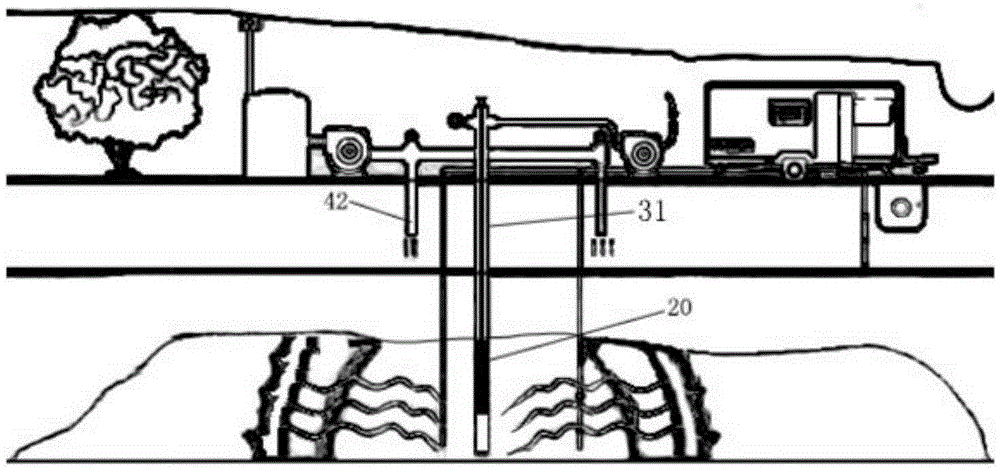
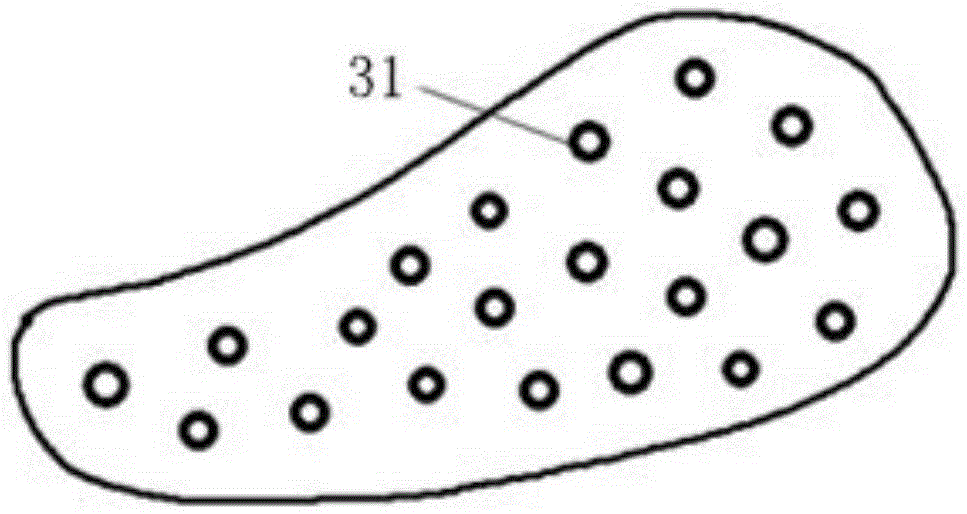
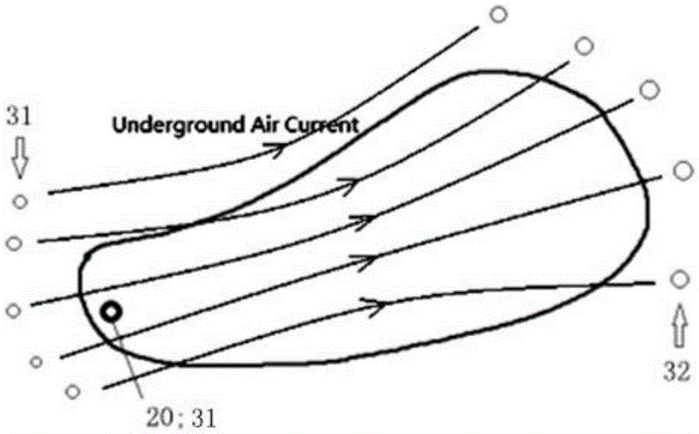
[0038] This embodiment provides an in-situ smoldering system, which uses smoldering to ignite the polluted area in the underground soil, so that the polluted area (i.e. the lower figure 1 the trapezoidal region shown in , and figure 2 and image 3 The flammable organic pollutants in the quasi-elliptical area shown in ) decompose water and CO2 after smoldering, and part of the VOCs and SVOCs are volatilized into gases after being heated, and then escape from the soil, and then are pumped by the polluted gas. The extraction device collects and discharges the volatilized gas to complete soil remediation. first reference figure 1 As shown in the accompanying drawings of the prior art, the in-situ smoldering system of this embodiment is the same as the in-situ smoldering system of the prior art, including an air injection well 31 for injecting air into the polluted area, and an ignition device 20, The ignition device 20 is used to increase the temperature near it, so that under...

Embodiment approach

[0044] It should be noted that the air injection well 31 and the gas phase extraction well 32 in this embodiment are not limited to the above-mentioned one embodiment, but can also be:

[0045] A kind of embodiment of described air injection well 31 and gas phase extraction well 32 is: it only comprises image 3 Several air injection wells 31, ignition device 20, and a gas phase extraction well 32 on the left side of the center, generally, in order to facilitate the ignition device 20 to enter the polluted area, preferably at least one air injection well 31 is stretched into the polluted area Among them, the ignition device 20 is movably arranged in the air injection well 31 . In this modified implementation, all the air injected from the multiple air injection wells 31 is collected at the gas phase extraction well 32 .

[0046] Another embodiment of the air injection well 31 and the gas phase extraction well 32 is: the air injection well 31 is arranged near the center of the...


PUM


Abstract

The invention provides an in-situ smoldering system. The in-situ smoldering system comprises an air injection device, ignition devices, a vapor extraction device and sealing cloth, wherein the air injection device comprises at least one air injection well which is used for injecting air into soil for smoldering of organic contaminants in a contaminated area, the ignition devices are arranged in the contaminated area and located close to the air injection device, the vapor extraction device comprises at least one vapor extraction well which extends into a soil aerated zone in the contaminated area and is used for extracting air and volatile organic pollutants, and the sealing cloth is laid on the soil surface on the upper portion of the contaminated area and used for inhibiting the organic pollutants and the air from escaping from the soil surface. The in-situ smoldering system further comprises the multiple air injection wells and the multiple vapor extraction wells, wherein the air injection wells and the vapor extraction wells are distributed outside the contaminated area, and the air pressure difference between the air injection wells and the vapor extraction wells forces the air injected from the air injection wells to flow to the vapor extraction wells so that the air can be spread and distributed in the contaminated area. According to the in-situ smoldering system, the use number of the air injection wells and the ignition devices can be effectively reduced.

Description

technical field [0001] The invention relates to the technical field of soil remediation using smoldering combustion, in particular to an in-situ smoldering system. Background technique [0002] Soil is the final destination of various pollutants, and the accumulation of pollutants has become one of the main environmental problems. Organic pollutants pollute the soil after entering the soil, and cause secondary pollution to surface water and groundwater, directly or indirectly endangering human health. In recent years, the problem of organic soil pollutants in my country has become increasingly prominent, posing a serious threat to the ecological environment, food safety and human health. [0003] In-situ smoldering remediation technology is an excellent solution for remediating VOCs (volatile organic compounds) and SVOCs (semi-volatile organic compounds) and other flammable organic pollutants in the soil. Inject air into the polluted area to decompose flammable organic pol...

Claims


Application Information

Patent Timeline
Patent Type & Authority Applications(China)
IPC IPC(8): B09C1/06
CPCB09C1/06
Inventor 张秋子李书鹏孙尧刘阳李季李庆崔双超
Owner BCEG ENVIRONMENTAL REMEDIATION CO LTD
Learn More