Multi-rotor-wing unmanned aircraft

A multi-rotor unmanned and aircraft technology, applied in the field of unmanned aircraft, can solve the problems of poor environmental adaptability, poor flight stability, etc., and achieve the effect of maintaining stability, high flight stability, and shortening the time for adjusting balance

Inactive Publication Date: 2016-02-03
JIYI ROBOT SHANGHAI
View PDF7 Cites 4 Cited by
  • Summary
  • Abstract
  • Description
  • Claims
  • Application Information

AI Technical Summary

Problems solved by technology

[0004] In view of the defects in the prior art, the purpose of the present invention is to provide a multi-rotor unmanned aerial vehicle to solve the technical problems of poor environmental adaptability and poor flight stability existing in the existing multi-rotor unmanned aerial vehicle

Method used


Image

  • Multi-rotor-wing unmanned aircraft
  • Multi-rotor-wing unmanned aircraft
  • Multi-rotor-wing unmanned aircraft

Examples


Embodiment 1

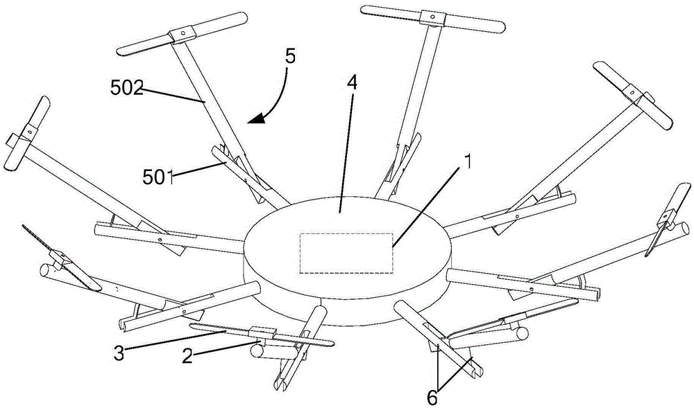
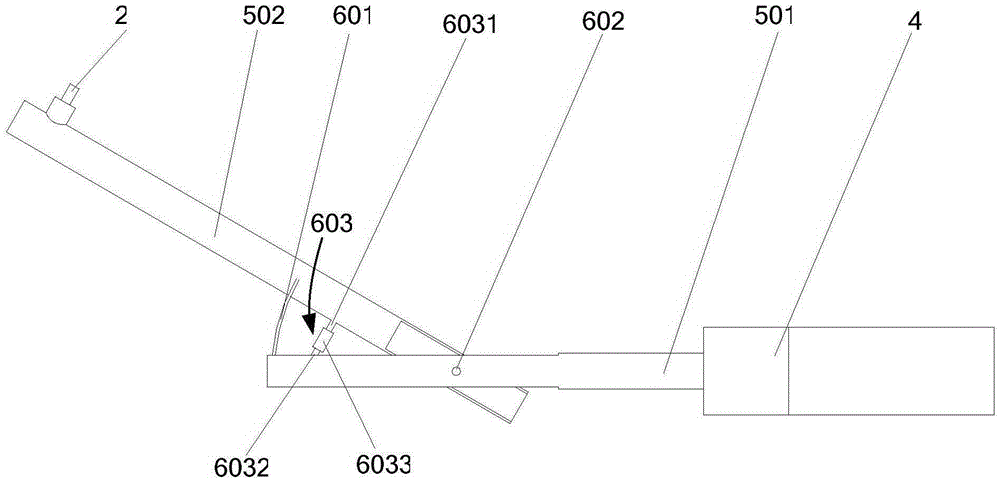
[0028] Such as figure 2 As shown, the connecting piece 6 includes: a reed 601, a pin shaft 602 and a tension member 603. The pin shaft 602 is arranged on the side close to the body 4 to connect with the strut 501 and the swing rod 502 respectively, and the reed 601 is arranged on a side far away from the body 4. One side is respectively connected with the strut 501 and the swing rod 502 , the tension member 603 is arranged between the pin shaft 602 and the reed 601 , and the tension member 603 is respectively connected with the strut 501 and the swing rod 502 .

[0029] The tension member 603 includes an upper screw 6031, a lower screw 6032 and a threaded tube 6033. The upper screw 6031 is connected with the swing rod 502, the lower screw 6032 is connected with the strut 501, and the threaded tube 6033 is connected with the upper screw 6031 and the lower screw 6032 respectively. The upper screw 6031 and the lower screw 6032 are provided with external threads, and the upper an...

Embodiment 2

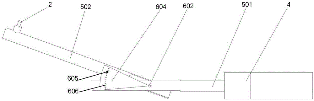
[0033] Such as image 3As shown, the connector 6 includes: a fan-shaped block 604, a pin shaft 602 and a latch 605. The circular center of the fan-shaped block 604 is arranged on the side close to the body 4 and is respectively connected to the strut 501 and the swing rod 502 through the pin shaft 602. The fan-shaped block 604 The arc end of the arc end is arranged on the side away from the body 4, and the lower plane of the sector block 604 is connected with the swing rod 502, and a plurality of positioning holes 606 are arranged on the arc inner side of the arc end of the sector block 604, and the bolt 605 is provided with threads, correspondingly Specifically, a threaded hole is provided on the swing rod 502 at a position corresponding to the positioning hole, and the pin 605 is screwed to the swing rod 502 through the positioning hole 606 .

[0034] The process of adjusting the inclination angle between the propeller 3 and the body 4 using the connector structure of this e...

Embodiment 3

[0037] Such as Figure 4 As shown, the connector 6 includes: a pin shaft 602, a push rod 607, a slider 608 and a locking block 609. The pin shaft 602 is arranged on the side close to the body 4 to connect with the strut 501 and the swing rod 502 respectively, and the slider 608 is arranged The side away from the body 4 is socketed and connected with the strut 501. The strut 501 is provided with external threads, and the locking block 609 is provided with internal threads. , the push rod 607 is connected with the swing rod 502 and the slider 608 respectively.

[0038] The process of adjusting the inclination angle between the propeller 3 and the body 4 using the connector structure of this embodiment is as follows:

[0039] When the external wind is strong and the inclination angle between the propeller 3 and the body 4 needs to be increased, the locking block 609 on the inside of the slider 608 is rotated inwardly, and then the slider 608 is slid inwardly, and the slider 608 ...


PUM


Abstract

The invention provides a multi-rotor wing unmanned aircraft which comprises a flight control assembly, a rack, a plurality of motors and a plurality of propellers. The rack comprises a machine body, a plurality of supports and a plurality of connectors. The flight control assembly is arranged on the machine body, each support comprises a supporting rod and a swing rod, the supporting rods are connected with the machine body, and one end of each swing rod is movably connected with the corresponding supporting rod through the corresponding connector. The included angles between the supporting rods and the swing rods are changeable, the motors are connected to the other ends of the swing rods, and the propellers are connected with the motors. According to the multi-rotor-wing unmanned aircraft, the angles between the supporting rods and the swing rod are adjustable, and adjustment of the inclined angles between the propellers and the machine body are achieved; the inclined angles between the propellers and the machine body can be adjusted according to the specific flight environment, the aircraft can adapt to various flight environments, the flight stability can be effectively maintained in various flight environments, and the aircraft has the advantages of being wide in application range and high in flight stability.

Description

technical field [0001] The invention relates to an unmanned aerial vehicle, in particular to a multi-rotor unmanned aerial vehicle with stable operation. Background technique [0002] In recent years, multi-rotor UAVs have become one of the hotspots in the research field of emerging micro UAVs. Multi-rotor unmanned aerial vehicles have the advantages of small size, light weight, low cost, flexible operation and high safety, and can be widely used in aerial photography, detection, search and rescue, exploration and other fields. [0003] The multi-rotor unmanned aerial vehicle is driven by multiple independent motors, the motors are connected to the frame, and the propellers are connected to the motors. Generally, the frame and fuselage of the multi-rotor unmanned aerial vehicle are arranged in the same plane, and the propellers are arranged horizontally. Therefore, the propeller of the multi-rotor unmanned aerial vehicle is arranged in parallel with the fuselage. This stru...

Claims


Application Information

Patent Timeline
Patent Type & Authority Applications(China)
IPC IPC(8): B64C27/52B64C27/08
Inventor 周剑锋王凯
Owner JIYI ROBOT SHANGHAI
Why Eureka
Try Eureka