
Adjustable Optical Coating Fixture

An optical coating and adjustable technology, applied in sputtering coating, ion implantation coating, vacuum evaporation coating and other directions, can solve the problem of no longer applicable, reduce coating cost, save tedious labor, shorten coating cycle Effect

Active Publication Date: 2017-09-12
BEIJING GUOWANG OPTICAL TECH CO LTD
View PDF3 Cites 1 Cited by
  • Summary
  • Abstract
  • Description
  • Claims
  • Application Information

AI Technical Summary

Problems solved by technology

[0004] In order to solve the problem that the existing coating fixtures are only aimed at single-size and single-shape substrates to be coated and are no longer applicable when the size and shape of the substrate to be coated changes, the present invention provides a clamp that can hold different sizes Adjustable optical coating fixtures for different shapes of substrates to be coated

Method used


Image

  • Adjustable Optical Coating Fixture
  • Adjustable Optical Coating Fixture
  • Adjustable Optical Coating Fixture

Examples


Embodiment Construction

[0031] The present invention will be described in further detail below in conjunction with the accompanying drawings.

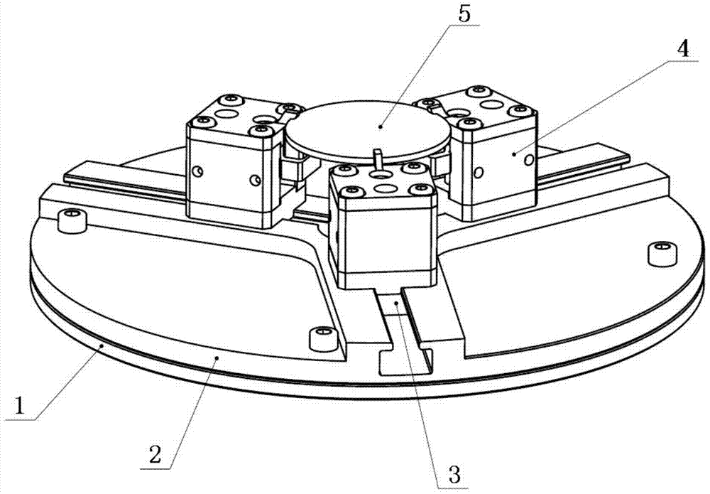
[0032] An adjustable optical coating fixture of the present invention is installed on a fixture bearing seat in a vacuum coating machine to clamp the substrate 5 to be coated.

[0033] Such as figure 2 As shown, the adjustable optical coating fixture of the present invention includes: a connecting member 1 , a fixed guiding member 2 , a plurality of sliding members 3 , and a plurality of clamping members 4 . Wherein, the number of sliding members 3 and clamping members 4 is the same.

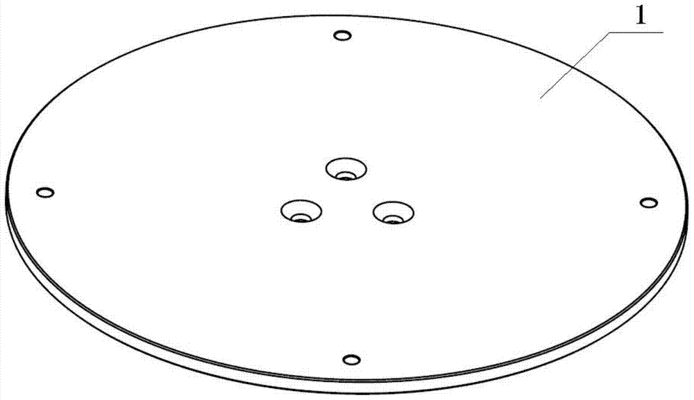
[0034] Such as image 3 As shown, the connecting member 1 is in the shape of a disk as a whole, and there are three openings evenly distributed on the central circumference of the connecting member 1, which are used to be fixedly connected with the clamp bearing seat in the vacuum coating machine. There are four holes evenly distributed on the outer circumference of the conn...


PUM


Abstract

The adjustable optical coating fixture relates to the field of optical coating, which solves the problem that the existing coating fixture only targets single-sized and single-shaped substrates to be coated and is no longer applicable when the size and shape of the substrate to be coated change. . The invention comprises a connecting member; a fixed guide member with a plurality of T-shaped slots; a sliding member correspondingly installed in the T-shaped slot and matched with the T-shaped slot; the clamping member includes three support frames fixed on the The lead screw on the support frame, the slider set on the lead screw, and the flexible part fixed on the slider; the protruding structure on the edge of the upper support frame is in contact with the upper surface and side of the substrate to be coated, and the upper surface of the flexible part is in contact with the film to be coated The lower surface of the substrate is in contact; the sliding member is connected with the lower supporting frame through locking screws, and the sliding member and the lower supporting frame are clamped and fixed to the T-shaped groove of the guiding member through the locking screws. The invention realizes the clamping of substrates to be coated with different sizes and shapes, shortens the coating cycle and reduces the cost.

Description

technical field [0001] The invention relates to the technical field of optical coating, in particular to an adjustable optical coating fixture. Background technique [0002] Vacuum coating technology is to use physical and chemical means to coat the surface of solid materials with a layer of coating with special properties, so that the surface of solid materials has wear resistance, high temperature resistance, corrosion resistance, oxidation resistance, radiation protection, electrical conductivity, magnetic conductivity, and insulation. And decoration and many other superior properties than the solid material itself. At present, vacuum coating technology has been widely used in aviation, aerospace, electronics, information, machinery, petroleum, chemical industry, environmental protection, military and other fields. [0003] When using a vacuum coating machine to coat a thin film on the surface of the substrate 5 to be coated, it is necessary to use a clamp to hold the su...

Claims


Application Information

Patent Timeline
Patent Type & Authority Patents(China)
IPC IPC(8): C23C14/50
Inventor 时光张立超梅林才玺坤武潇野贺健康隋永新杨怀江
Owner BEIJING GUOWANG OPTICAL TECH CO LTD
Learn More