Downhole controllable nuclear magnetic resonance well logging during drilling device

A nuclear magnetic resonance and well logging technology, which is used in electronic magnetic resonance/nuclear magnetic resonance detection, analysis by nuclear magnetic resonance, wellbore/well components, etc. and other problems, to achieve huge economic and social benefits, improve drilling efficiency, and save drilling time.

Active Publication Date: 2016-02-03
BC P INC CHINA NAT PETROLEUM CORP +2
View PDF10 Cites 10 Cited by
  • Summary
  • Abstract
  • Description
  • Claims
  • Application Information

AI Technical Summary

Problems solved by technology

[0006] The above-mentioned prior art NMR logging tool requires a combination of multiple sets of low-gradient-high-gradient magnetic field regions, so multiple main magnets with opposite magnetic poles are required to be arranged axially, resulting in a long string of instruments and a complex structure; at the same time, the drilling time increases , drill tool assembly vibration, etc., resulting in obvious degaussing of the main magnet of the probe, offset of sensitive areas, and distortion of measurement data
In addition, the existing NMR measurement methods and instruments while drilling can only measure signals at a single depth, and cannot measure formation information at different depths from the borehole wall

Method used


Image

  • Downhole controllable nuclear magnetic resonance well logging during drilling device
  • Downhole controllable nuclear magnetic resonance well logging during drilling device
  • Downhole controllable nuclear magnetic resonance well logging during drilling device

Examples


Embodiment Construction

[0021] Hereinafter, the implementation of the technical solution will be further described in detail with reference to the accompanying drawings.

[0022] Those skilled in the art can understand that although the following description relates to many technical details related to the embodiments of the present invention, this is only an example for explaining the principle of the present invention, and does not mean any limitation. The present invention can be applied to occasions other than the technical details exemplified below, as long as they do not deviate from the principle and spirit of the present invention.

[0023] In addition, in order to avoid limiting the description of this specification to cumbersomeness, in the description of this specification, some technical details that can be obtained in the prior art materials may be omitted, simplified, modified, etc., which is important to the technology in the field. It is understandable for personnel, and this will not affe...


PUM


Abstract

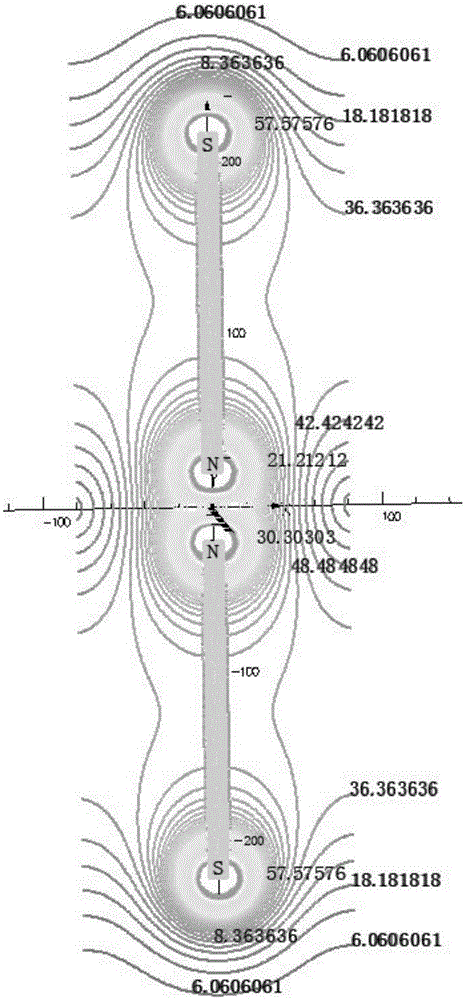
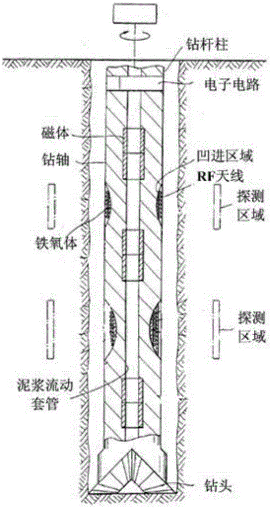
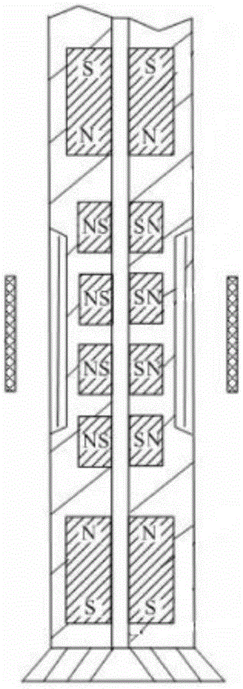
The invention discloses a downhole controllable nuclear magnetic resonance well logging during drilling device. The device comprises an axially and vertically arranged device body, an electronic circuit part and a measurement probe part, wherein the device body is supported by a non-magnetic drill collar (10); the upper side of the device body is connected with a drill bit driving part (1), and the lower side of the device body is connected with a drill bit (11); the device body is provided with an axial mud channel (3) through which drilling fluid flows; the electronic circuit part is accommodated in an electronic circuit cabin (2) and is used for receiving and processing a signal from the measurement probe part; the measurement probe part comprises a main magnetic body pair consisting of two axially arranged main magnetic bodies (4a and 4b) with opposite magnetic poles; the two main magnetic bodies (4a and 4b) are symmetrically arranged in the axial direction relative to the axial center of the device body; the axial distance between the two main magnetic bodies can be changed.

Description

Technical field [0001] The invention relates to the technical field of petroleum drilling engineering, in particular to a nuclear magnetic resonance measurement method and instrument used for real-time measurement of geological parameters of the formation around a borehole during geological exploration and development drilling operations. Background technique [0002] Nuclear magnetic resonance logging while drilling refers to the method and technology of nuclear magnetic resonance measurement during the drilling process, which can determine the irreducible water saturation, permeability and identify oil and gas before drilling fluid invasion occurs. This technology can perform comprehensive evaluation of the formation of the wellbore trajectory in real time, adjust the trajectory direction in time with the wellbore trajectory data, keep the wellbore going through the target layer, and play an important role in improving the recovery rate and efficiently developing complex oil and...

Claims


Application Information

Patent Timeline
Patent Type & Authority Applications(China)
IPC IPC(8): E21B49/00G01V3/32G01N24/08
Inventor 毛为民王鹏艾维平洪迪锋张程光管康范锦辉彭浩
Owner BC P INC CHINA NAT PETROLEUM CORP
Why Eureka
Try Eureka