Pipe replacing and slurry discharging device for slurry shield and slurry discharging mode

A mud-water shield and pipe row technology, which is applied in the direction of earth square drilling, mining equipment, tunnels, etc., can solve the problems of waste of bentonite slurry, increase of construction cost, impact of tunnel cleaning, etc., achieve fast discharge speed, reduce usage, reduce The effect of construction costs

Active Publication Date: 2016-02-03
CHINA RAILWAY ENGINEERING EQUIPMENT GROUP CO LTD
View PDF5 Cites 12 Cited by
  • Summary
  • Abstract
  • Description
  • Claims
  • Application Information

AI Technical Summary

Problems solved by technology

The disadvantage of this device is that the discharge of the slurry from the mud pipe is slow and the waiting time is long. The operator always starts to change the pipe before the slurry is completely discharged, and the mud is directly discharged into the tunnel; in addition, the mud extension system The sewage tank below is limited by space, resulting in insufficient slurry storage volume. In addition, it is difficult to completely match the slurry pumping speed of the sewage pump and the slurry discharge speed of the mud pipe, resulting in the slurry overflowing from the sewage tank or pumping out
It is difficult to achieve zero discharge of slurry by using this conventional slurry discharge device, which has a great impact on the cleaning of the tunnel, and at the same time causes waste of bentonite slurry and increases construction costs

Method used


Image

  • Pipe replacing and slurry discharging device for slurry shield and slurry discharging mode
  • Pipe replacing and slurry discharging device for slurry shield and slurry discharging mode
  • Pipe replacing and slurry discharging device for slurry shield and slurry discharging mode

Examples


Embodiment Construction

[0013] The following will clearly and completely describe the technical solutions in the embodiments of the present invention with reference to the accompanying drawings in the embodiments of the present invention. Obviously, the described embodiments are only some, not all, embodiments of the present invention. Based on the embodiments of the present invention, all other embodiments obtained by persons of ordinary skill in the art without making creative efforts belong to the protection scope of the present invention.

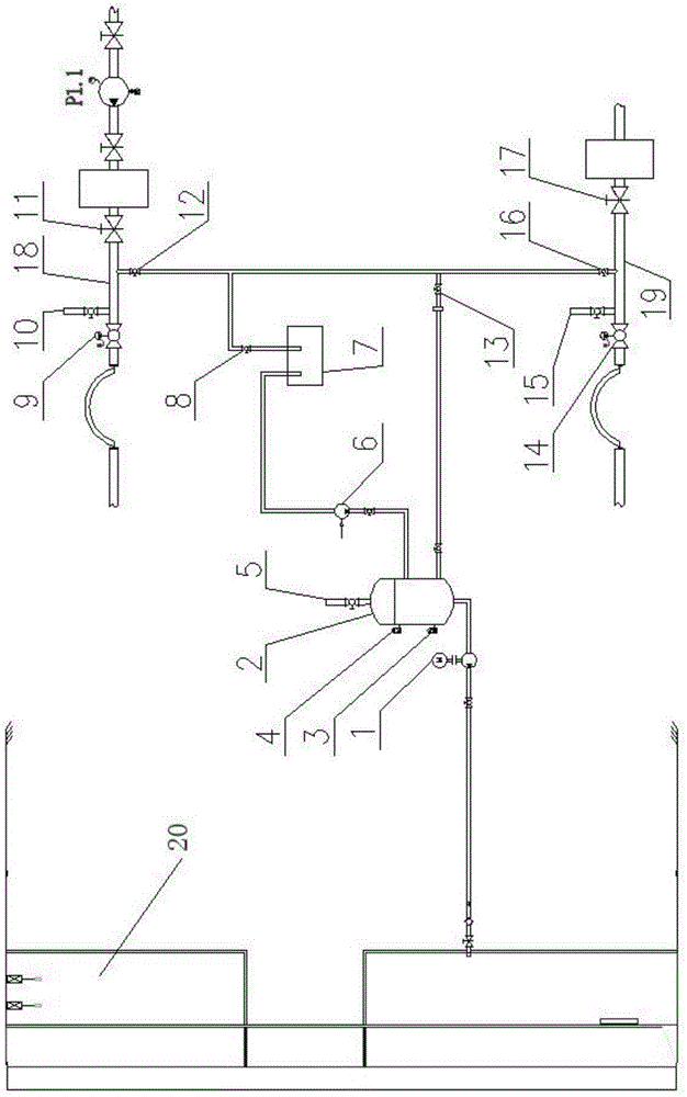
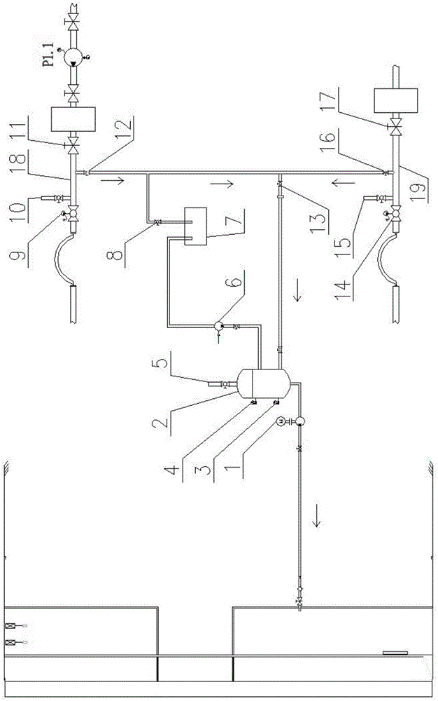
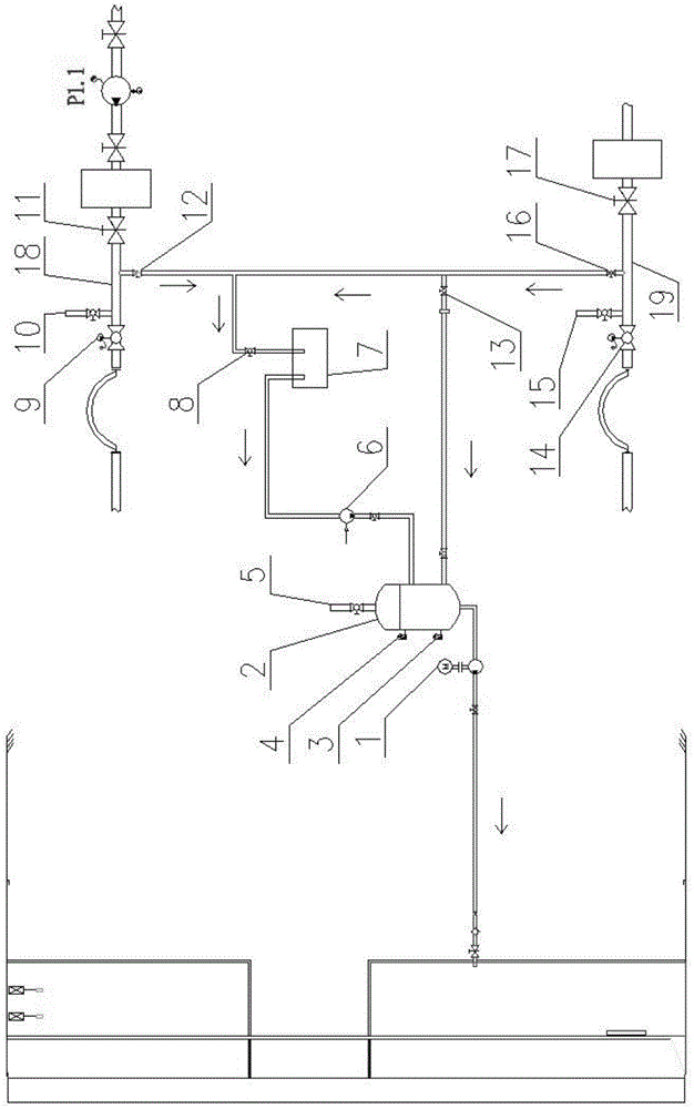
[0014] Such as figure 1 As shown, the muddy water shield pipe replacement and slurry discharge device of the present invention includes a sewage pump 1 connected to the air cushion warehouse 20, the sewage pump 1 is connected to the closed slurry storage tank 2, and the closed slurry storage tank 2 is provided with an upper liquid level sensor 4 and a lower level sensor 4. The liquid level sensor 3 and the breathing port 5 of the slurry storage tank, the slurr...


PUM


Abstract

The invention provides a pipe replacing and slurry discharging device used for a slurry shield and capable of quickly discharging slurry in a slurry pipe without leakage and a slurry discharging mode. The pipe replacing and slurry discharging device comprises a sewage pump and an airtight slurry storage tank, wherein a slurry inlet of the airtight slurry storage tank is divided into two ways, one way is connected with a slurry inlet pipe through a slurry inlet pipe ball valve and connected with a slurry discharging pipe through a slurry discharging pipe ball valve after being provided with a master control ball valve, the other way is connected with a sewage tank through a membrane pump, and the sewage tank is connected with the slurry inlet pipe ball valve and the slurry discharging pipe ball valve respectively through a sewage ball valve. A slurry inlet pipe control ball valve and a slurry inlet pipe gate valve are arranged at the two ends of the slurry inlet pipe, a slurry inlet pipe breathing port is formed between the slurry inlet pipe control ball valve and the slurry inlet pipe gate valve, a slurry discharging pipe control ball valve and a slurry discharging pipe gate valve are arranged at the two ends of the slurry discharging pipe, and a slurry discharging pipe breathing port is formed between the slurry discharging pipe control ball valve and the slurry discharging pipe gate valve. The pipe replacing and slurry discharging device used for the slurry shield is high in slurry discharging speed, can be basically free of leakage, ensures tunnel cleaning, decreases the using amount of a slurrying agent and facilitates environmental protection, and the construction cost is reduced.

Description

technical field [0001] The invention relates to the field of mud-water shield machines for tunnel construction, in particular to a mud-water shield waste slurry discharge system. Background technique [0002] At present, with a large number of tunnel constructions at home and abroad, the shield machine has become the first choice. With its excellent pressure control performance, the slurry shield is widely used in tunnel projects that cross rivers, seas, and have high requirements for settlement. During mud-water shield construction, the muck is transported out through the mud pipeline by the mud pump. The mud pipeline needs to be extended every time a certain distance is excavated. When extending, the mud pipe needs to be disconnected. The mud discharge in the mud pipe is a problem that needs to be solved. question. [0003] The conventional waste slurry discharge device is to discharge the mud in the tunnel mud pipe to the sewage tank below the extension system, and then ...

Claims


Application Information

Patent Timeline
Patent Type & Authority Applications(China)
IPC IPC(8): E21D9/13
Inventor 贾金建贺开伟叶超苏志学张中英张伟强
Owner CHINA RAILWAY ENGINEERING EQUIPMENT GROUP CO LTD
Why Eureka
Try Eureka