Supercharge Your Innovation With Domain-Expert AI Agents!

Mixers and their mixing components

A technology of mixers and inclined parts, applied in the direction of engine components, machines/engines, noise reduction devices, etc., to achieve smooth passage, reduce the risk of liquid film formation, and reduce the effect of backflow

Active Publication Date: 2017-09-26
TENNECO SUZHOU EMISSION SYST
View PDF1 Cites 0 Cited by
  • Summary
  • Abstract
  • Description
  • Claims
  • Application Information

AI Technical Summary

Problems solved by technology

However, there are certain disadvantages of mixers of this construction

Method used


Image

  • Mixers and their mixing components
  • Mixers and their mixing components
  • Mixers and their mixing components

Examples


Embodiment Construction

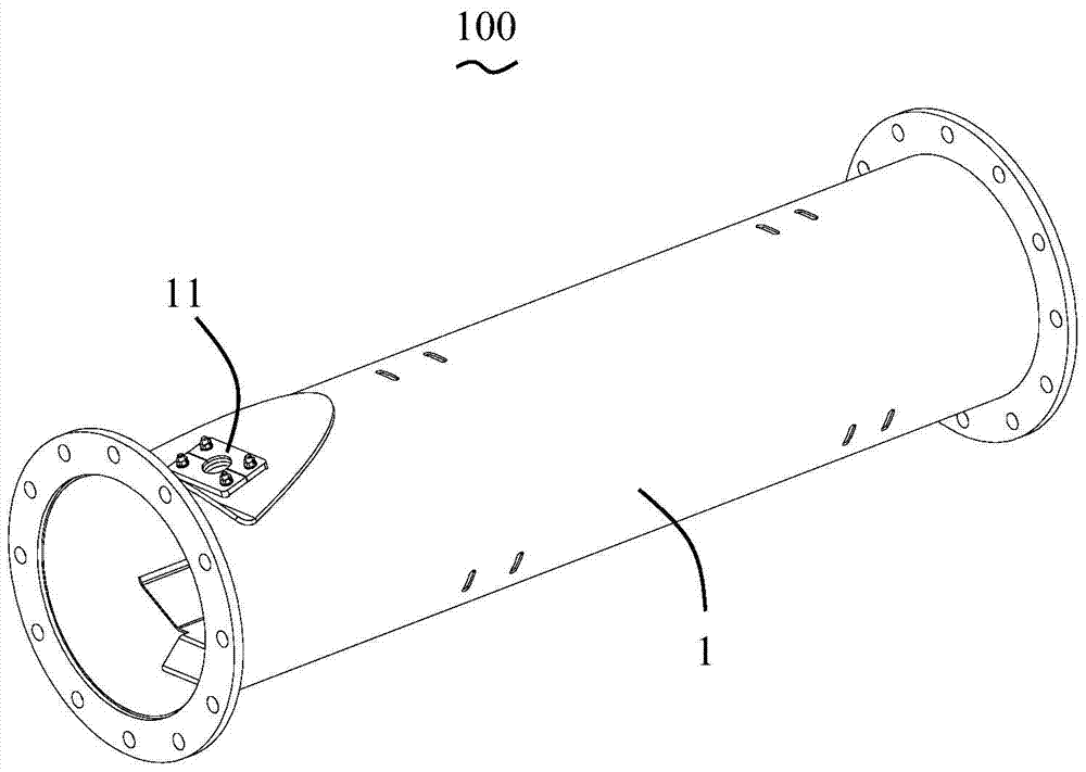
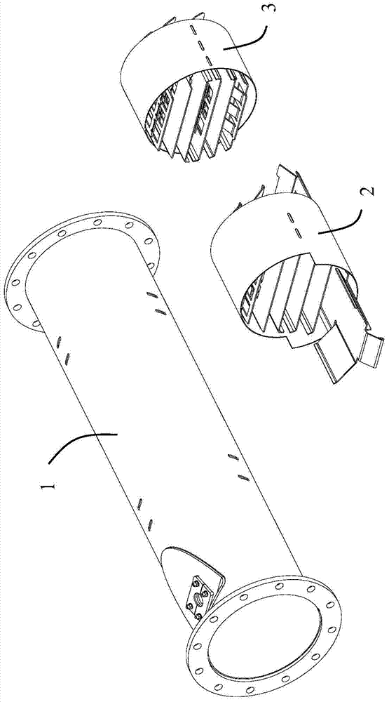
[0048] Please refer to Figure 1 to Figure 3 As shown, the present invention discloses a mixing assembly 100 , which includes a mixing tube 1 , a mixer 2 inside the mixing tube 1 , and a mixing element inside the mixing tube 1 and downstream of the mixer 2 . Please refer to figure 2 and image 3 As shown, in the first embodiment of the invention, the mixing element is a further mixer 3 . The mixing pipe 1 is provided with a urea nozzle installation part 11 for installing a urea nozzle (not shown), and the mixer 2 and another mixer 3 are located downstream of the urea nozzle installation part 11 . It can be understood that when the mixing assembly 100 of the present invention is installed in an exhaust gas after-treatment system, an oxidation catalyst (DOC) and / or a diesel particulate filter (DPF) may be provided upstream of the mixing assembly 100 , a selective catalytic reduction (SCR) may be provided downstream of the mixing assembly 100 .

[0049] When working, the ure...


PUM


Abstract

A mixer and its mixing assembly are used to mix urea droplets with engine exhaust, the mixer includes a support part and several plates fixed on the support part and stacked, the plates It includes a plate-shaped portion and an inclined portion extending obliquely from the plate-shaped portion to the downstream of the exhaust direction. The inclined portion is used to fully mix the urea droplets with the exhaust gas of the engine. The inclined portion further extends horizontally downstream in the exhaust direction. Such setting enables the airflow to pass through the mixer smoothly, reduces backflow, reduces the risk of forming a liquid film, and is not easy to form urea crystals.

Description

technical field [0001] The invention relates to a mixer and a mixing assembly thereof, which belong to the technical field of engine exhaust aftertreatment. Background technique [0002] Studies have shown that the uniformity of ammonia distribution in the pipeline of exhaust aftertreatment systems (such as selective catalytic reduction systems, SCR systems) has an important impact on the overall performance and durability of the system. If the distribution of ammonia is not uniform, it will lead to excessive ammonia in local areas, which will easily cause ammonia leakage, and the conversion efficiency of nitrogen oxides (NOx) will be too low in other ammonia-lean areas. The uneven distribution of ammonia over a long period of time can lead to uneven catalyst aging, which affects the overall performance of the catalyst. In addition, the uneven distribution of urea droplets will cause the temperature of the local pipe wall or mixing structure to be too low, forming crystalli...

Claims


Application Information

Patent Timeline
Patent Type & Authority Patents(China)
IPC IPC(8): F01N3/28F01N13/00
Inventor 殷雷郑祥赵治国
Owner TENNECO SUZHOU EMISSION SYST
Features
  • R&D
  • Intellectual Property
  • Life Sciences
  • Materials
  • Tech Scout
  • Unparalleled Data Quality
  • Higher Quality Content
  • 60% Fewer Hallucinations
Learn More